Now that is a very Revit blog title, for sure 🙂

So I had a nice old Curtain Wall Panel Door family, which had a nested ‘container’ Generic Model family…

old2bversion-7701979

… in which I arrayed a shared, nested Door Panel Generic Model Family. Basically, it allowed for automatic stacking and sliding doors of varying numbers of panels living inside a Curtain Wall Panel Door, all working automatically. You could tag and edit the Comments and Mark of the nested Panel, but couldn’t change its visibility.

This means that things like slide direction arrows were a problem. I previously had some messy approach to arrows and offsets, but there were tied to the array so they were not flexible enough. As the only parameters that I could access for the shared, doubly-nested panel were Comments and Mark and Image, I couldn’t really use these in visibility parameters or formulas. I wanted to be able to turn off and on arrow annotation (for slide direction), and also set a Keynote or taggable text parameter for ‘FG’ (fixed glass)  or ‘SL’ (sliding) and so forth.

What’s the answer?

For one thing, I’m sorry but you probably have to ditch the array. It is simply too difficult to link through parameters to the elements inside an array, plus you probably really don’t want to.

So, save a backup of your ‘array’ family and rebuild it to use individually placed family instances with visibility parameters based on the ‘Array number’ you had before. You will have 2 panels that have their visibility set to a parameter with a formula like “Array number = 2”. You will have to duplicate all of your elements for each set, and constrain them all individually. This is a pain, but if you want to get the sub-element visibility control, you may think it is worth it. You will have to do this for as many array conditions as you want to cover (like 2, 3, 4 etc).

With this new ‘non array’ family, how do we set up the parameters?

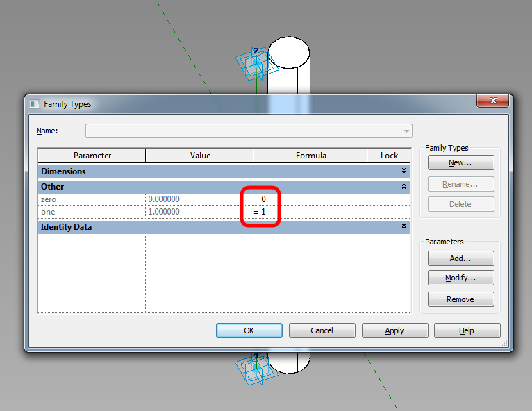
We are going to drive all of it with a single integer value instance parameter in the shared panel family. Then we will tie that to element visibility parameters.

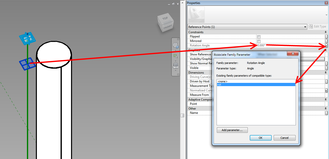
We will link that integer instance parameter through each level like so:

instance2bparam2blinking-9187315

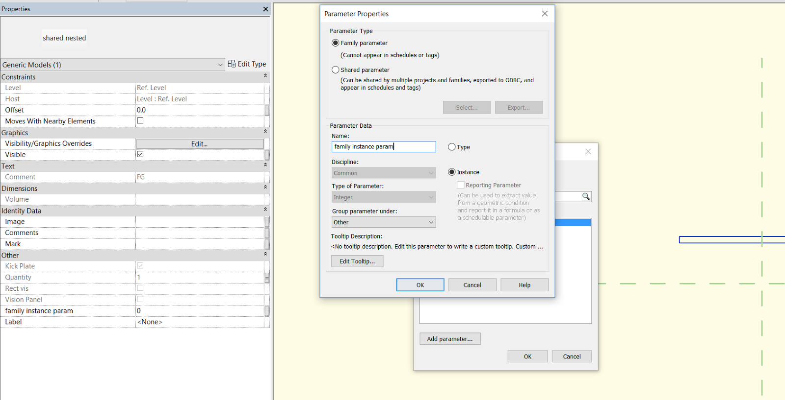
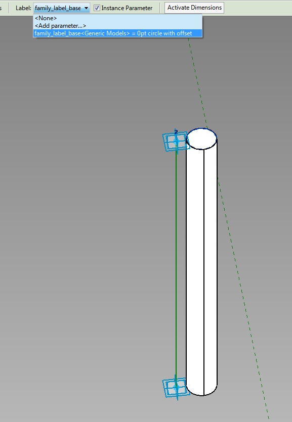
… until we get to our ‘container’ that used to hold an array, but now holds individual family instances that we turn on and off with the array number. From here, we make a new instance parameter for each placed family instance, so we can drive the nested family. So for a three panel sliding family, we might have 3 instance parameters in the ‘container’, like:

  • Left Panel vis type (used for 2 and 3 panels)
  • Centre Panel vis type (used in the 3 panel type only)
  • Right Panel vis type (used for 2 and 3 panels)

Link these three parameters through to the Curtain Wall Door family (they can be instance or type here at the parent family). They are now accessible in the project. Essentially, we can select our Curtain Wall Door family, modify the 3 integers, which drives through all the way to our most deeply nested Panel family.

In the deeply nested Panel family, we use the integer to drive other things, like:

  • turn Plan and Elevation arrows on and off, 
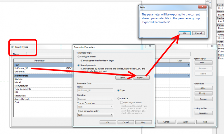
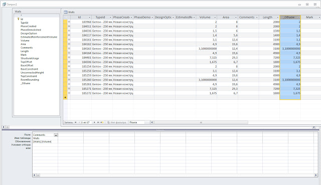
  • set a Shared text parameter to a certain value (with a nested IF statement). Note: Add the Shared text parameter to a Generic Model tag and you can tag and schedule it in the project. 
  •  show / hide model geometry

Note: You can’t use Keynote here because we are not allowed to drive a Type Parameter with our instance parameter.

param_linked-6748504

Unfortunately, we can’t drive a Material parameter directly with the integer value. But, we can have multiple copies of geometry with different materials, and drive the Material visibility with the above process.

Finally, you can do this structure as many times as you like, but obviously the amount of integers you have to keep track of is going to get more and more difficult. You will also need some way of explaining to users what each integer actually does – like if I set the Left Panel to integer 1, what will show up and what will the tag value be? You will probably need some kind of explanatory schedule or document for this…

But there you have it, a framework for driving deeply nested shared family visibility. Congratulations if you made it to the end of the post 🙂

By now, most of us are using Navisworks for some sort of aggregation, model checking or clashing.  So why would anyone want to use Revit Inteference Check (on the Collaborate tab, Coordinate panel)?  Basically, because its “in-canvas” and doesn’t require workflow-disconnect (export NWC, find Clash, Switchback, modify, refresh NWC).

Instead, we can run a clash report within Revit, close the dialog, fix the problem, then refresh the report.  Much easier.

For one recent Basement Carpark Design, we already had Parking families set out, and the Structural model linked in.  All I had to do was edit the Parking family, add a Shared Nested family of suitable Category (in my case, Electrical Equipment), run the Interference Check, fix or mark up the problems, and then switch “off” the shared nested component (using a visibility switch on the shared nested component).  Quick and easy.

Obviously, there is a lot it can’t do (especially compared to Navis), but some things it can do nicely.  Read on for some Q and A:

Is there a limit to the Categories you can use in an Interference Check?
Yes, see image below

Can you clash against a Shared Nested form of one of the above Categories?
Yes!

Can you clash against a Linked file in Revit?
Yes, of course – the above Category limitation still applies

Can you clash against selected objects?
If you select objects before starting the command, only items matching above Category limitations and present in the selection will be available as a tick box.

Will collinear 3D faces trigger a Interference in Revit?
Unfortunately yes.  You can work around this by offsetting one of the forms by 1 or 2mm to “ignore” those clashes.

Will an invisible (unchecked) Extrusion or Family be included in the Interference Check?
No

Will an item that is completely transparent (either based on a View setting or Material setting) be included in the Interference Check?
Yes

Can you clash against a Void form?
Yes

While you can’t “Save” a Search Set, you can Refresh your previous Interference Check in Revit.  Just do this:
Interference Check – Show Last Report – Click Refresh
Note: pressing “Refresh” does not re-run the Check, it just re-checks the things already in the list to see if any have been fixed.

To make “finding” the clashes quicker after the report is run – open a few key views first.  As these are in memory, when you click “Show” on an item in the report, Revit will look in these open views first.

Helping google:
Revit interference checking shared nested

To make the swappable profile, use a Generic Model Adaptive template, but don’t add any Adaptive points.  Set the 2 reference planes in the template to “Defines Origin”.  You can parametrize this as much as you like (just don’t use Reference Lines – you need a closed profile of Model Lines as per any Profile).  Then, load this into another new Generic Model Adaptive family.  Host the Profile component on a hosted point (that is, one that has been placed on a line).  You will need one of these nested Profiles at each end of a line to control the form properly.

I am in the habit of using hosted points to host Profiles now.  For example, in a 2pt Adaptive with a Reference Line, I will add 2 hosted points to the Reference Line to carry the Profile instances.  These hosted points will be forced to the end points by using a parameter for zero, and another one for one, and forcing these values by putting 0 and 1 in the Formula box of the Family Types dialog (see image).

If you are using hosted points (make a new point, and drop it on a Reference Line – it will be come a small dot if it is hosted on the line), you can actually adjust the rotation Angle using a parameter – this makes it easy to rotate the profile around the hosting line.

Here is the really cool part – you can apply a Label parameter to the Profile instance in the host family, and then directly swap Profile shapes (different nested RFAs or types in the same RFA, both work).  This even works from the Project Environment.

If you want to drive the profiles parametrically via the host family, you will have to make them un-Shared (otherwise you can’t map parameters from Type to Host).  You can swap between un-Shared and Shared profiles using the Label parameter.

Finally, to create the form, select the Profile families (the ones at each end of the Reference Line) and click Create Form.  Unlike other form creation scenarios, you do not want to select the “lines” by Tabbing through – you actually want to select the family itself.  The Label parameter will allow you to swap these families, which will drive the Form.

In the image below, all of these are one Adaptive family – with profiles swapped, and parameters adjusted, including rotation about the axis.


Download the above example here

Credit:  I’m fairly sure I read about this general idea somewhere… it was a while ago.

In the Parameter Properties dialog, click Export.

Note:  The Export option is not enabled if the selected parameter is already in the current shared parameter file.

A message displays informing you that the shared parameter will be exported to the shared parameter file you set up in Step 1.

Here is the rest of the how-to:
Exporting Shared Parameters to a Shared Parameter File – WikiHelp
Edit:

You can export from the Family or Project environment. If you already have a SP with the same name in your current SP file, you will need to switch to a blank SP file, export the parameter, and then possibly you can “hack” it into your current file by text editing the SP files (maybe).

Revit doesn’t let you tag Wall Volume by default, so Avisotskiy puts RDBLink to good use – he uses Microsoft Access to update a Shared Parameter with the wall Volume data, and then simply uses a tag to grab the manually updated and manually created Volume data.

This is not a ‘live’ link, but it shouldn’t take too long to round trip the project to update the Volume information prior to document transmission or printing.

From his blog:
Revit does not allow to directly make a mark in the volume of the object.

4. Unload in Access, using the Query Designer update the “_Obem”, taking data from the parameter “Volume”.

Image from http://avisotskiy.blogspot.com.au/


via
Google Translate
of
http://avisotskiy.blogspot.com.au/2012/03/revit-db-link.html

EDIT For some reason the original video is not working.  It was also referenced on Wikihelp here, and that embedded version is broken too.  I tried to contact Youtube user cwm9 but did not get a reply.  I have re-uploaded to here:
http://www.youtube.com/watch?v=RuYely7lu-0&feature=youtu.be

Wow 🙂

Broken version, was at: http://www.youtube.com/watch?feature=player_embedded&v=mVHgJFrBvC0

From the narrator (?):


“Uploaded by cwm9 on Dec 3, 2011


The coordinate system or Revit has been rehashed many times on blogs and posts, but has been clear as mud for me, and I suspect a lot of other people. So I took the time to really figure out it, and here’s a 30 minute explanation of how Revit’s coordinate systems work, interrelate,
how true north works, and how to put multiple copies of a building on a site.”

Issue

You want to update a revision/issue title block label globally in multiple sheet views without the need to edit every single individual sheet view.

Solution

The following steps explain how to add a label to a titleblock, which can be updated globally in multiple sheet views.

via
Autodesk – Autodesk Revit Architecture Services & Support – You want to update a revision/issue title block label globally in multiple sheet views

While discussing an interesting baluster-with-lighting family, Steve reminds us that “Revit hates switching between shared and not shared status.”

You have to follow a strict process of deleting and / or renaming affected families that exist in the project if you wish to switch them from Shared to non-Shared, or vice-versa.

If you want to read the rest of Steve’s, post, here is a link:
Revit OpEd: Dept. of Quirky – Baluster with Light Fixture

Great veteran’s tip from Steve.  He explains how to reset shared coordinates to an out-of-the-box setting by Acquiring Coordinates from a default Revit template:

Once two files are sharing coordinates you can’t really remove this relationship. If you remove the link and import it again (Auto – Origin to Origin) the relationship survives.


To truly remove (really more like replace) the relationship I use a new file that is based on the stock Revit template default.rte. I import this file and Acquire Coordinates from it instead. Revit can only acquire coordinates from one source file so using a “good” one “resets” it

via
Revit OpEd: Shared Coordinates and Copy Monitor

So you have added a bunch of Shared Parameters to your Project, but you never bother to set the ‘Group Parameter under:’ property correctly…you are naughty, aren’t you?

It can make using Revit a lot easier if you Group Parameters properly – its what revit wants you to do.

How do you do it?  Quite simply:

  1. Manage – Project Parameters
  2. Select Parameter – Modify
  3. Change ‘Group Parameter under:’ property to something more appropriate.
  4. OK, OK etc
Here is a quick video on how to do it:
Annoyingly, you can’t change the grouping of parameters that are ‘built in’ to Revit.  It annoys me that ‘Drawn By’ is not grouped with Checked By, Approved By and Designed By on the Sheet Parameters:
If you know how to fix this, please comment!