Have you ever had a large facility, divided up into Levels and Sectors, and you wanted to find out in which zone a particular item or group of items exist?

In Navisworks, this can be a real pain because guess what – Navisworks doesn’t know about “stuff”, only about surfaces. In other words, if an item is fully contained within the volume of another item, this doesn’t show up as a clash. Theoretically, you could have a facility full of pipes that are clashing with ducts, and as long as the pipes run perfectly inside the shell of the duct, the clash won’t show in Navisworks. Scared?

Interestingly, Revit Interference Check does know about stuff. It can find clashes of one item inside another, such as:

So, if you have access to the Revit models of items that you want to clash to see if any are “inside” others, Revit Interference Check can do that for you.

Now, before I move on… I did investigate some options for forcing Navisworks to do this type of detection for me. My first idea was setting the clash detection tolerance to a negative. In essence, these moves things around to see if they will hit each other. Set it to 500mm and it will find items that are 499mm apart. But it was too heavy handed to find what I wanted. So my next idea was to slice up the model in Revit before exporting to Navisworks and detect that way (basically giving me more surfaces to work with). Here are the steps I took:

  1. Modelled the sector level zones as Floor elements in Revit
  2. Made the Floor have a new layer at every 100mm (ie. 45 layers for 4500mm floor to floor)
  3. Divided all these Floors into Parts – meaning I had slices at every 100mm
  4. Exported the 3D view from Revit to DWF with Parts Visibility set to show both– in this way, you get both the original Floor and the resulting Parts. Using the Convert Parts option in Navisworks Exporter gives you one or the other, but not both… I imported this 3D DWF to Navisworks and used it for clash detection.
  5. Using some search sets, I was able to use the Part “slices” to discover where items existed, but I couldn’t easily relate that back to the original Floor element (which had a manually input property for the Sector in the Comments field in Revit). An addin that drives parameters from original Floors into their child Parts would help here…

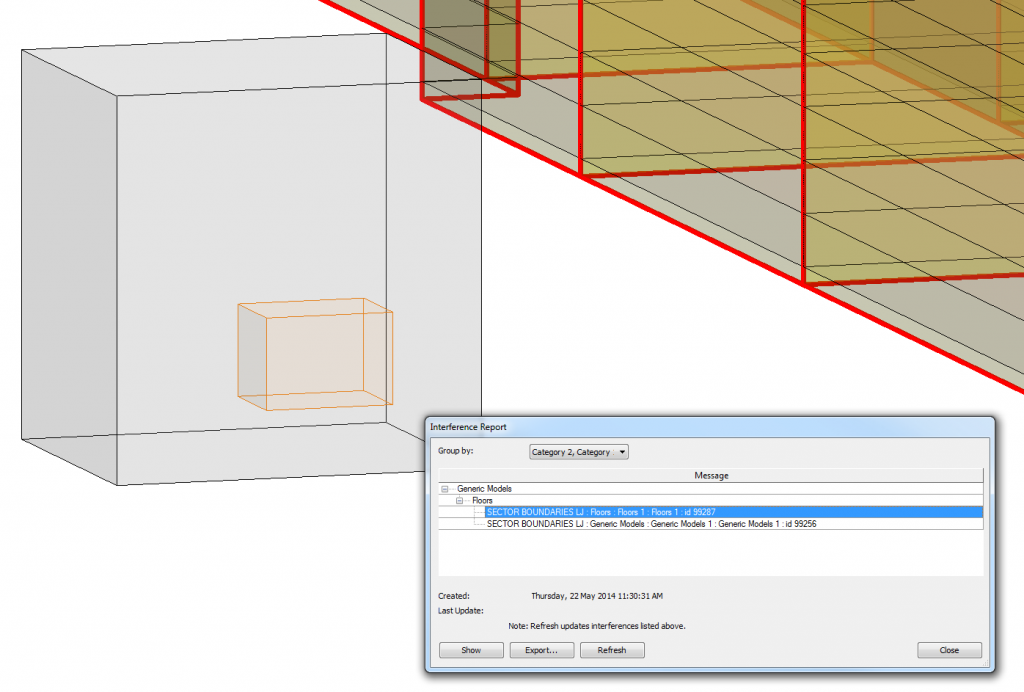
So, back to treasure hunting in Revit… If you have access to the Revit models (or IFC) of the items you want to check, it is quite easy:

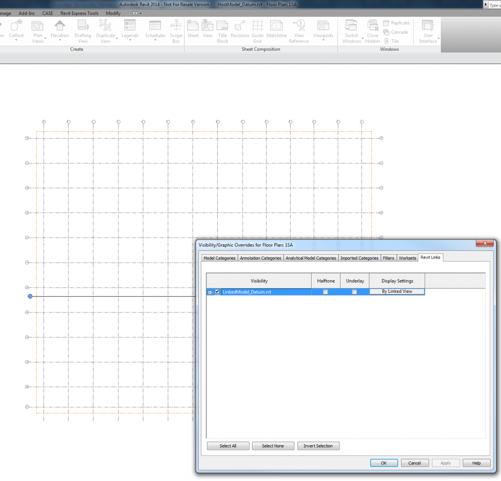
  1. Link the models together
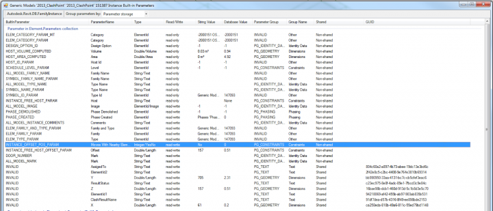
  2. Use Interference Check to determine which items are affected (see image above). Only certain categories are candidates for Interference Check, check the last column here.
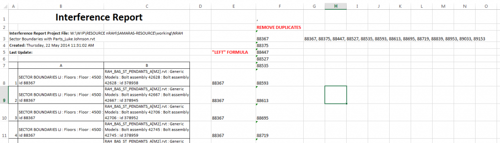
  3. Export the HTML report from Interference Check dialog
  4. Open in Excel
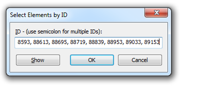
  5. Use a LEFT formula and Remove Duplicates to grab list of Element Ids
  6. Use CONCATENATE to put commas in
  7. Use Select by Id in Revit, and the string from 5) to select the affected elements in Revit
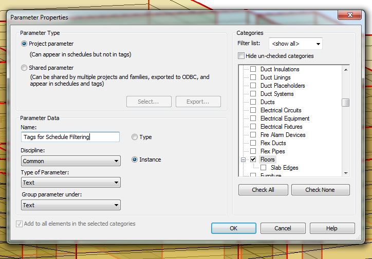
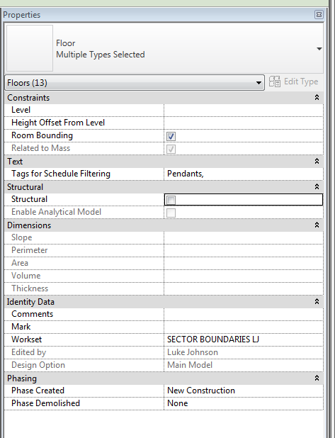
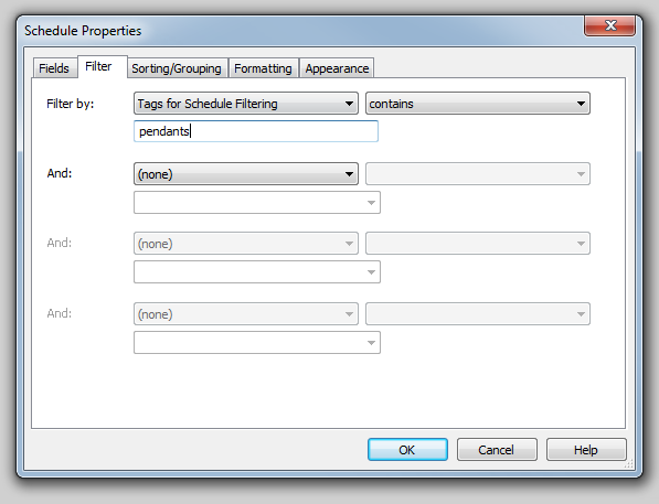
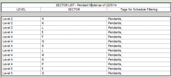
  8. Modify some property to allow for filtering. In my case, I made a “Tags” property so that I can search for “contains” in a Schedule and selectively show items. 

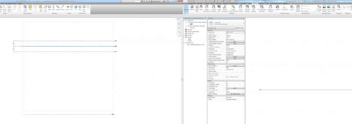
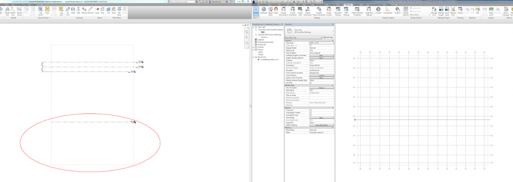
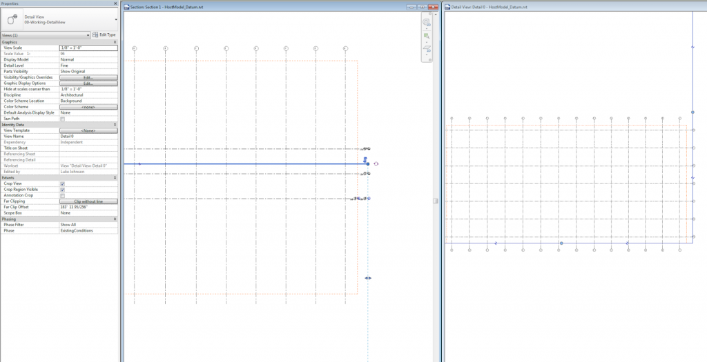
Here are some screenshots of those steps.

Another way to shortcut some of the above would be to drive different Type Names into each floor based on the two sector-level parameters (using an addin). In the Interference results, you can immediately see:
Workset
Category
Type
Element ID

At least then you wouldn’t have to go through the above Excel steps just to get the results into a Revit selection set!

To combine some workflows, if you don’t have access to the Revit model and you want to do this type of “container clashing”:

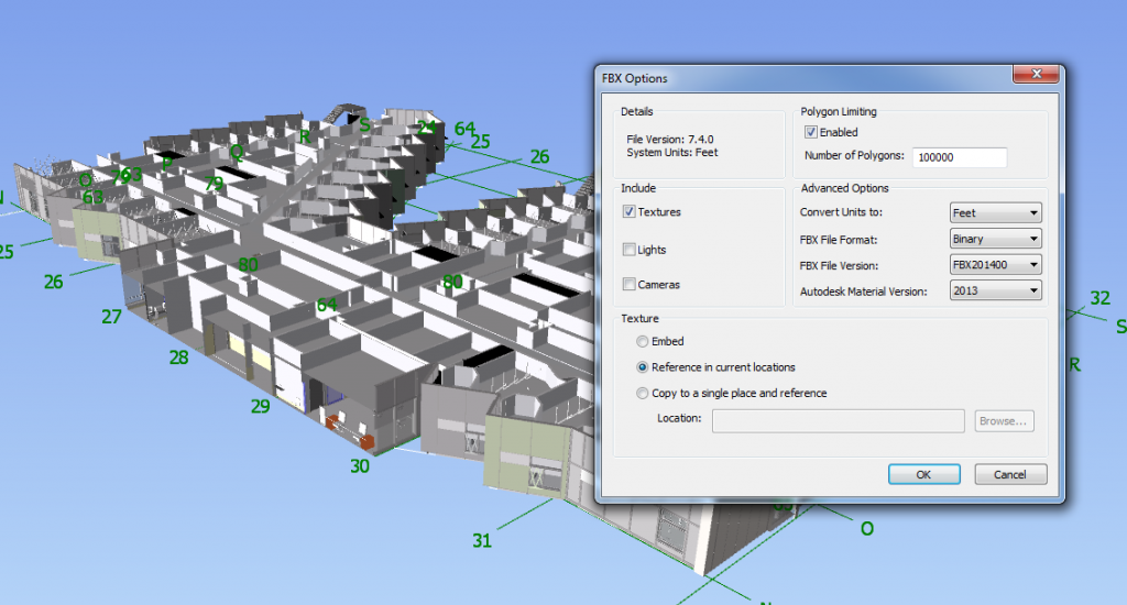
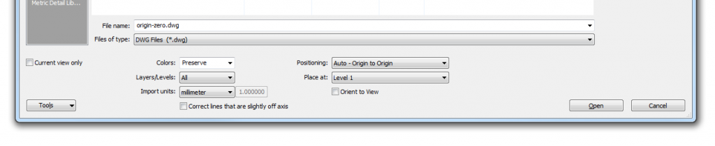
  1. Use the FBX to DWG workflow to get your items from Navisworks
  2. New Family – Generic Model
  3. Import DWG – Origin to Origin 
  4. Also place something at 0,0,0 (could use DWG origin locator for this)
  5. Save / Load family into Project
  6. Place the family at 0,0,0 (could use DWG origin locator for this)
  7. Use this Generic Model family as one of the parties in your Interference Check
  8. If you go this route (FBX-DWG-family), it will take super long to do the Check – go grab a drink or do something else for a bit
    (note: one nice thing about this is that the family is clashed as one single item – meaning the Interference Check results are quite clean)

Remember you can use “Show Last Report” on the Ribbon to get the last interference check results back.

The standing rule with linked datums is that if they intersect the view cutting plane, they should show up in the host. However, Matthew Nelson discovered an interesting inconsistency – for Plan Views, this doesn’t seem to apply when Scope Box has been added to Grids.

In other words, the Grids in the Linked project, when applied to a Scope Box, do not seem to show in the Host project, even if the Host plan view range intersects the Grid elements.

After some experimentation, including testing on Revit 2013, 2014 and 2015, I think I have found the solution:
If the Scope Box in the Link intersects the Level in the Link with the lowest Z value (the lowest level), then that Scope Box and any associated Datum (Grids and Reference Planes) WILL appear by default in the Host.

Got it? So this won’t work:

 But this will:

Download this to see it in action

There are 3 other ways to show linked Grids in a plan representation, even if you can’t modify the linked Scope Box as I describe above:

  • Make a Detail View with Plan Orientation that intersects the linked Scope Box
  • Copy / Monitor the Grids (which will automatically bring in the linked Scope Box too)
  • Use “By Linked View” setting in the Host

Here are those workarounds:

Copy / Monitor

Detail View

By Linked View


Revit-exportlayers-ifc2x3-forCOBie.txt: This is an updated export layers
table file. It is intended primarily for COBie, but can be used for any
export. It would replace your existing export layers table file.

Attachments
AdditionalExtendedFMHandoverViewFiles.zip

via
IFC for Revit / Wiki / Notes on support for Extended FMHandOverView

http://bimforum.org/wp-content/uploads/2014/04/BIMForum-BIM-BAM-BOOM-MacLeamy.pdf
http://bimforum.org/wp-content/uploads/2014/04/4-Boston-BIMForum-Tyler-Goss.pdf
http://bimforum.org/wp-content/uploads/2014/04/OptimizingBuildingLayouttoMinimizeWalkingDistances-Abstract.pdf
http://bimforum.org/wp-content/uploads/2014/04/5-Boston-BIMForum-Optimizing-building-layout-to-minimize-walking-distance-FINAL.pdf
http://bimforum.org/wp-content/uploads/2014/04/6-2014-04-19-Boston-BIMForum-Fralick.pdf
http://bimforum.org/wp-content/uploads/2014/04/RemoteSolvingOverviewDoc.pdf
http://bimforum.org/wp-content/uploads/2014/04/7-TTcoreStudio_BIMForum_FINAL_20140421.pdf
http://bimforum.org/wp-content/uploads/2014/04/9ab-2014-Professionals-Choice-BIM-Award-MASTER-FINAL-PPT-04172014.pdf
http://bimforum.org/wp-content/uploads/2014/04/14111_BIMForum_3pg.pdf
http://bimforum.org/wp-content/uploads/2014/04/TGP_Boston-BIMForum-Final.pdf
http://bimforum.org/wp-content/uploads/2014/04/11-Boston-BIMForum-spieler-chapa-5.pdf
http://bimforum.org/wp-content/uploads/2014/04/12-Panzura-Rapid-Fire.pdf
http://bimforum.org/wp-content/uploads/2014/04/WSP_Abstract.pdf
http://bimforum.org/wp-content/uploads/2014/04/14-UNIQUE_CHALLENGES_for_MEP_DESIGN.pdf
http://bimforum.org/wp-content/uploads/2014/04/BIM-Forum-Abstract.pdf
http://bimforum.org/wp-content/uploads/2014/04/15-Carrato-Boston-BIMForum.pdf
http://bimforum.org/wp-content/uploads/2014/04/BIM-Forum-Boston-Jason-Chen.pdf
http://bimforum.org/wp-content/uploads/2014/04/1c-Boston-BIMForum-PowerPoint_SOM_004.pdf
http://bimforum.org/wp-content/uploads/2014/04/2-Boston-BIMForum-Matt-Petermann-Architecture-group_FINAL.pdf
http://bimforum.org/wp-content/uploads/2014/04/3-Boston-BIMForum_Final_Ammon-1.pdf
http://bimforum.org/wp-content/uploads/2014/04/4-Global-eTraining-Presentation-corporate-generator-BIMForum2014-1.pdf
http://bimforum.org/wp-content/uploads/2014/04/Jason-Reece-Abstract-Spring-BIMForum-2014-FINAL.pdf
http://bimforum.org/wp-content/uploads/2014/04/JASON-REECE-BIMFORUM-FINAL.pdf
http://bimforum.org/wp-content/uploads/2014/04/BIMForum_paper_JB_draft_3.pdf
http://bimforum.org/wp-content/uploads/2014/04/6-BIMForum_Boston_Berkoe_Final_2.pdf

Read more and view videos at:Boston BIMForum Presentations | BIMForum

Firstly, make sure you have a model on Glue that you can access. Did you know that when you Glue something from Navisworks, it makes an NWD and puts it in a folder like this:
“C:UsersLuke JohnsonAppDataLocalNavisworksPlugin63baac4b-76c8-4ff8-9039-d51645fd1ddc.nwd”

Once you have a model on Glue that you would like to download and use as modelling context in Revit, make a new Navisworks file and:

  1. Append that model back to Navisworks from Glue (it will look like you opened an NWD, with Clashes, Search Sets and Viewpoints all appearing. This tells us that BIM 360 Glue stores all that information in the cloud, at least when the model “originated” in Navisworks.)
  2. Use this method to export FBX and import to AutoCAD at correct scale (Limit your Navis view to only the elements necessary for modelling context. For example, walls or facade only.)
  3. Save the DWG
  4. Make a new Revit file. I had problems using the Construction template – it seemed to break the coordinates somehow… In any case, when I just used “None” template, it worked fine.
  5. Link the DWG into Revit, Origin to Origin
  6. Do your Revit modelling (in the screenshots below, I modelled part of a roof)
  7. Glue the new roof directly from Revit (you may want to Hide the DWG file prior to Appending). This will create a new Model. On BIM 360 Glue, you now have the original model plus this new model from Revit.
  8. Go to Glue app in Windows and make a new Merged Model. Tick the boxes for the original model, and this new model from Revit.
  9. Back in Navisworks, we can either choose to Append the entire new merged model, or just the new “piece” that we modelled in Revit.

If you have consistently used origin-to-origin “Revit zero” linking and project internal coordinates, you shouldn’t have any problems.

Some screenshots:

Notes:
55mb NWD took about 20mins to Glue

In this test, I used 2015 versions of Navisworks and Revit

Try it out

Info on exporting from Revit to this viewer, from The Building Coder:
The va3c project landing page displays the main projects addressed:

  • viewer – HTML viewer
  • GHva3c – Grasshopper va3c exporter
  • RvtVa3c – Revit va3c exporter
  • 3DS Max – JSON Exporter Max Script
  • Sketchup – Export to DAE Collada & View
  • json – JSON sample files
  • va3c – web viewer for AEC models

Take a spin with the va3c viewer demo for a quick and immediate impression of what we have achieved so far.

Read the whole post:
The Building Coder: AEC Hackathon From the Midst of the Fray

In a recent Twitter experiment, I posted three different opinions of BIM and have been monitoring the response through Retweets. Here are the results (as these are embedded tweets, the results will change over time).

The results thus far appear to be overwhelmingly positive – that BIM is indeed “awesome”. I guess the majority of my Twitter followers are, unsurprisingly, supporters of BIM.

I’ll keep this page live as a checkpoint for the statistics – it will be interesting to drop in from time to time and see if the results change as more people from outside my Twitter circle weigh in on this BIM thing…

Jeremy Tammik has kindly upgraded and released BipChecker for Revit 2015, you can download it at:
https://github.com/jeremytammik/BipChecker

Steps to get it going:

  1. Download ZIP
  2. Extract
  3. Open SLN in Visual Studio 2013 Express (free)
  4. Right click on BipChecker in Solution Explorer and open Properties
  5. Go to Reference Paths and add your Revit program directory
  6. Build Solution

It should instantly be visible in Revit 2015, Addins, External Tools – even if you have Revit open. While it has many uses, immediately obvious are the fact that it shows whether a parameter is read-write and it also displays GUIDs for Shared Parameters. You can choose whether to display Instance or Type Parameters. Cool.

Here is some sample output: