The standing rule with linked datums is that if they intersect the view cutting plane, they should show up in the host. However, Matthew Nelson discovered an interesting inconsistency – for Plan Views, this doesn’t seem to apply when Scope Box has been added to Grids.
In other words, the Grids in the Linked project, when applied to a Scope Box, do not seem to show in the Host project, even if the Host plan view range intersects the Grid elements.
After some experimentation, including testing on Revit 2013, 2014 and 2015, I think I have found the solution:
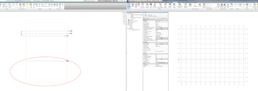
If the Scope Box in the Link intersects the Level in the Link with the lowest Z value (the lowest level), then that Scope Box and any associated Datum (Grids and Reference Planes) WILL appear by default in the Host.
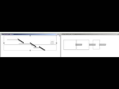
Got it? So this won’t work:

But this will:
Download this to see it in action
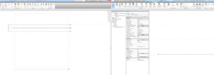
There are 3 other ways to show linked Grids in a plan representation, even if you can’t modify the linked Scope Box as I describe above:
- Make a Detail View with Plan Orientation that intersects the linked Scope Box
- Copy / Monitor the Grids (which will automatically bring in the linked Scope Box too)
- Use “By Linked View” setting in the Host
Here are those workarounds:
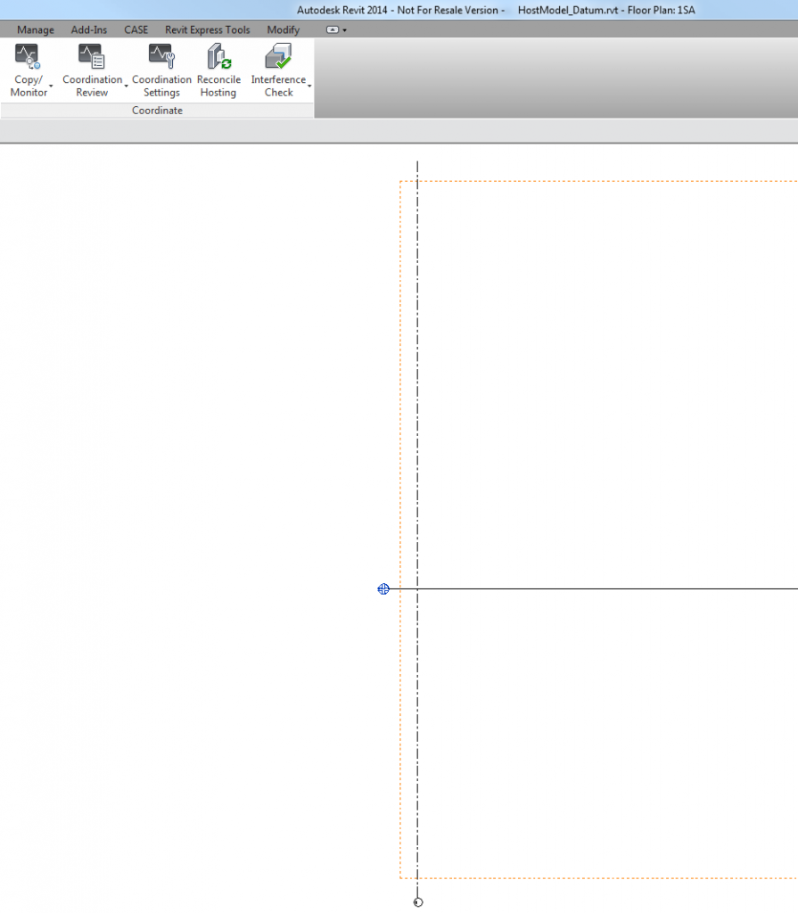 |
| Copy / Monitor |
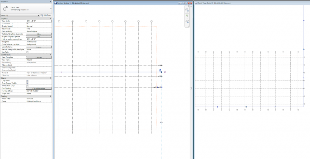 |
| Detail View |
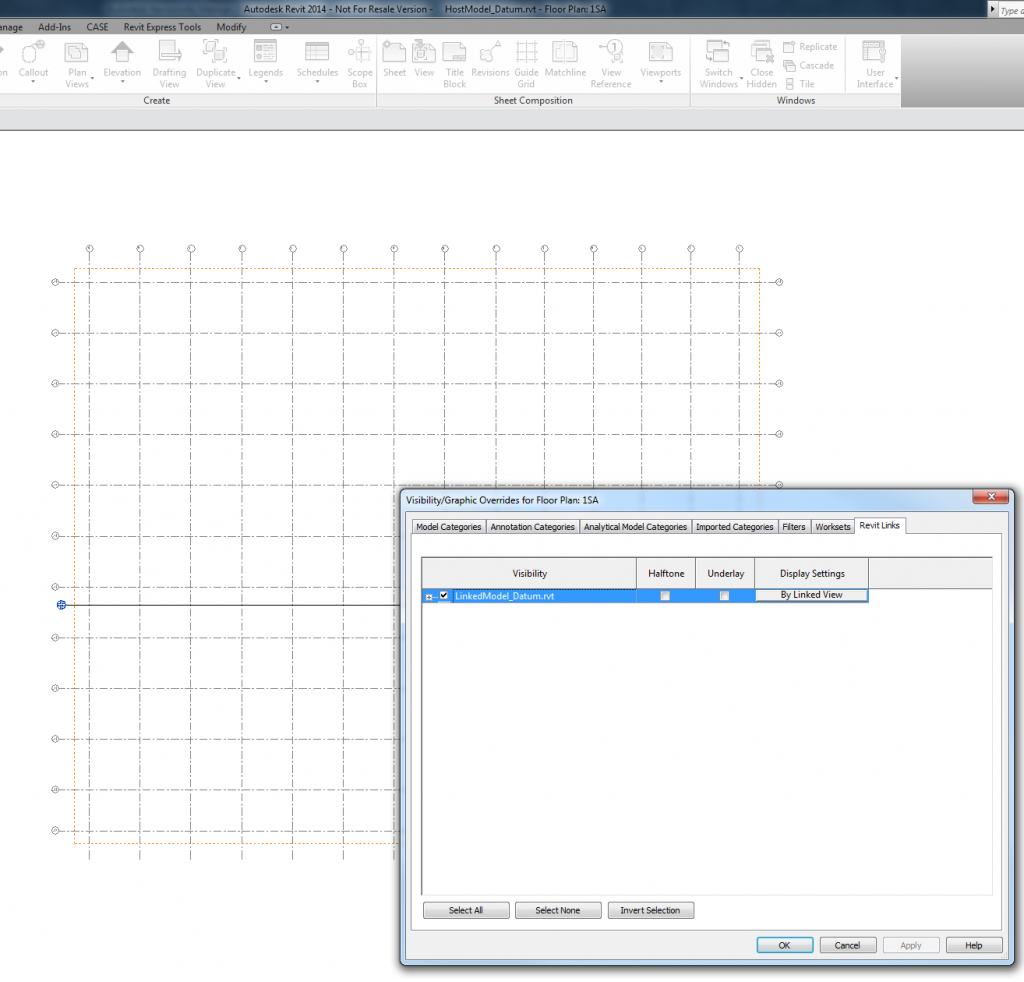 |
| By Linked View |