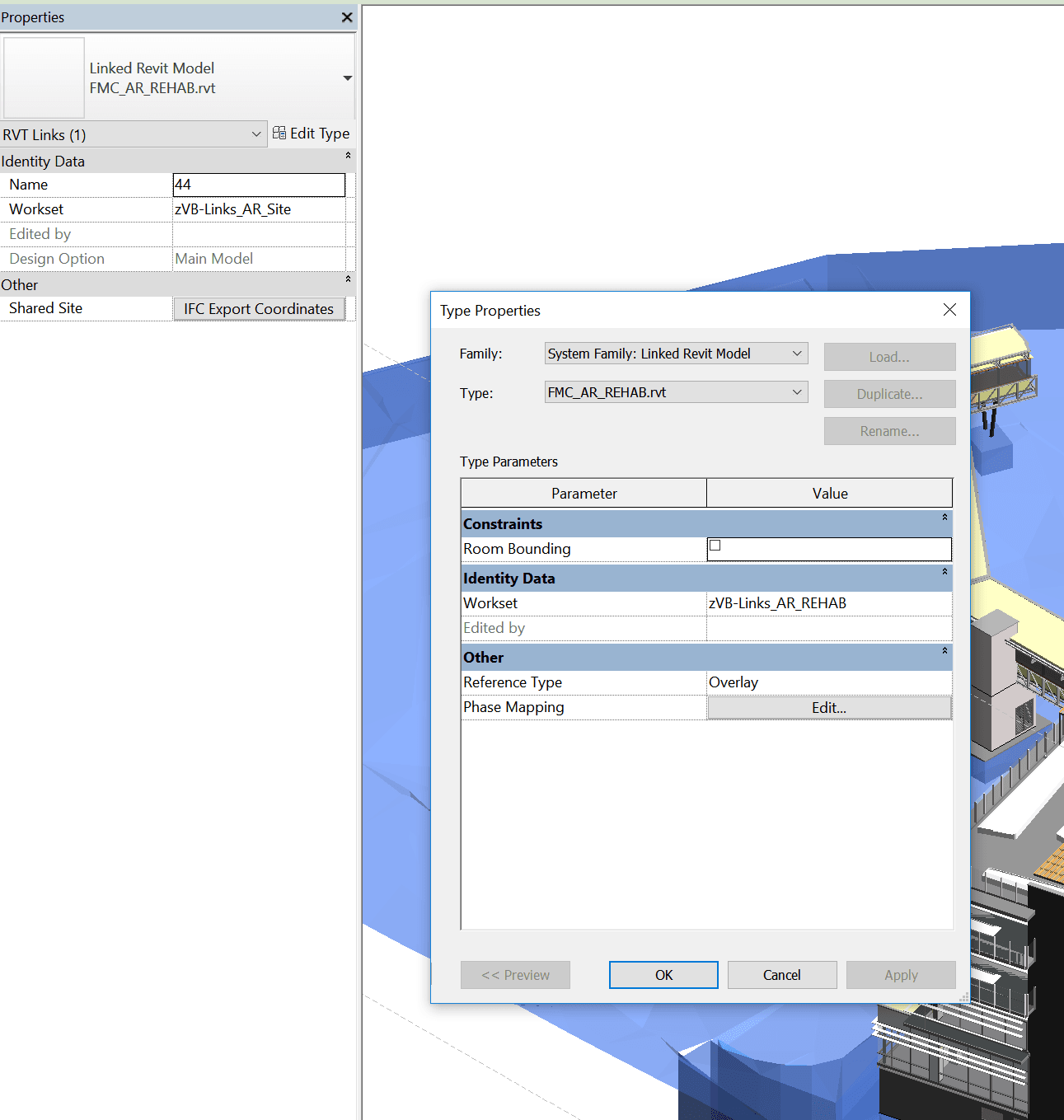
In Revit, each Link is bound to both a Type and an Instance. So you can have one Link ‘Type’ – relating to a single RVT file that is linked into the project. But it can be placed multiple times in the project, thus having multiple instances. In workshared projects, the Type and the Instance can belong to different Worksets.

Did you know you can use Linked Views to display two identical copies of the same linked model in different ways?

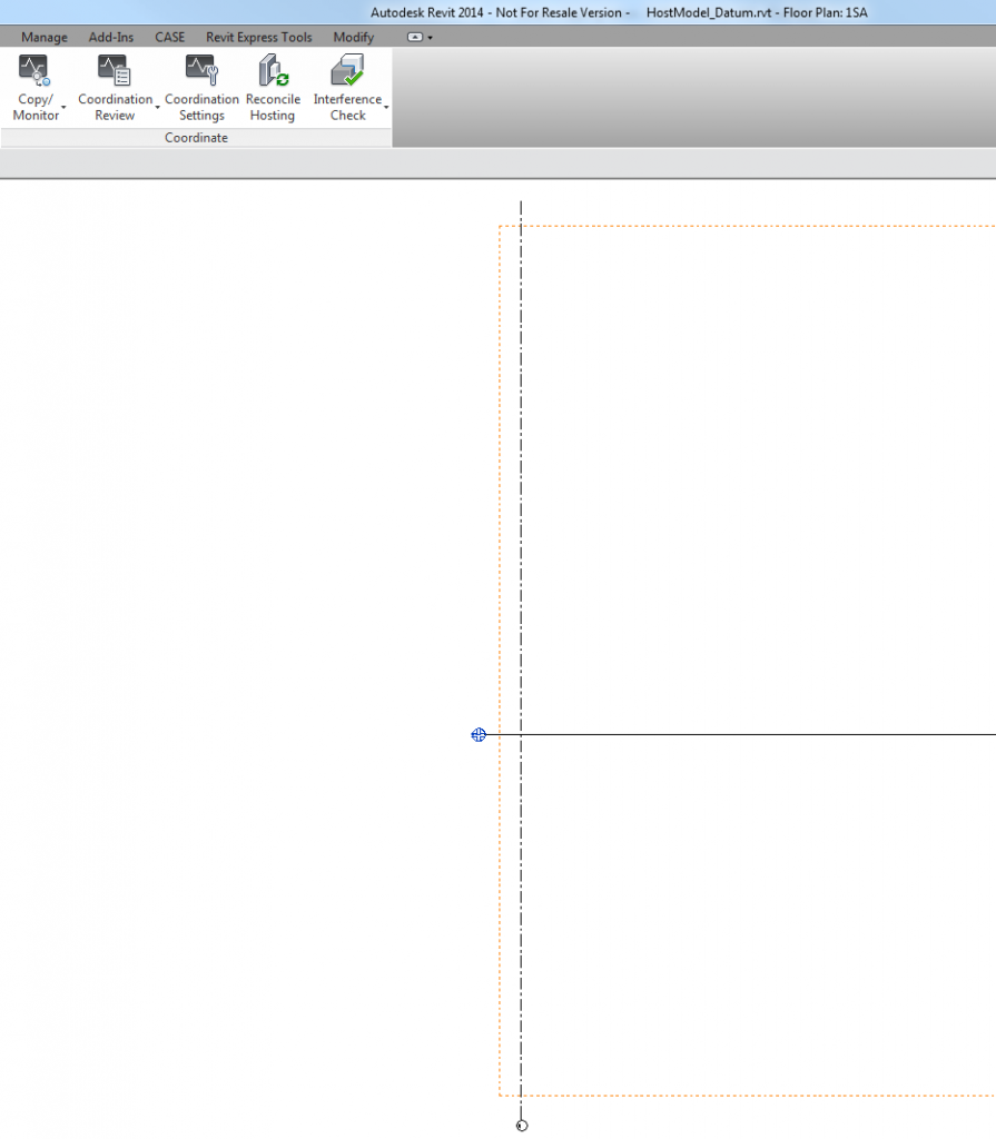
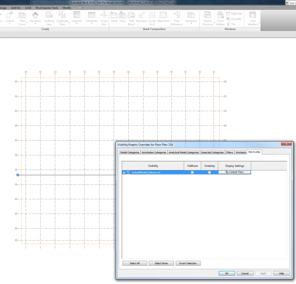
To add control, you should create 3 worksets – 1 for the Type, and 1 for each Instance, as shown below:

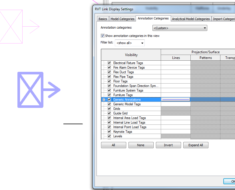
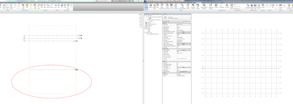
Then, set up two different Linked Views in that linked model. In this particular case, I want to use a model converted from ArchiCAD to a single Revit file. But I want to be able to separately load and display the Site objects, and the Building objects. So I have an Link Instance for each, and linked views for each. The whole rig can be seen in the image below.

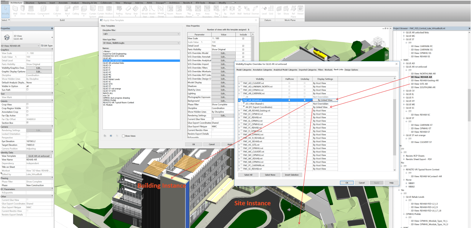
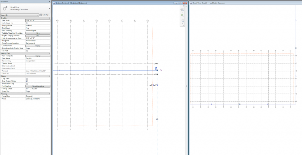
Using the worksets, I can separately Load / Unload each Instance (closing a Workset unloads any Link instances on that Workset from memory). And using the Linked Views and Overrides for the Instance, I can display each instance as I like. I can also load both instances and show both in a ‘combined’ view.

Final note: Link Instances can be located in different positions in the Host model, and they can have different Shared Coordinates. Using the methods above, you have a lot of flexibility to be able to use a single linked Revit model in many different ways…

Oh wait, you can’t… put more simply, you cannot override the lineweight of Generic Annotations for a linked file. In fact, it turns out you can’t override lineweights for anything, including Model elements in a linked file… you are stuck with them. You can Transfer Project Standards into the link but that is a painful workaround.

You can override the colour and linetype, no problem. But no matter what you try: Object Styles, Visibility Graphics, Revit Link Visibility overrides, none of this overrides the actual Lineweight of Generic Annotations in the linked file. It is using the value from the Line Weight settings, Annotation Line Weights tab IN THE LINKED file to draw these items in the host file. If Pen 1 is set to 0.3mm in the Link, you will never be able to get a lighter pen weight override in the Host.

To me, this is a bug. If the Revit Link visibility is set to Object Styles – By Host File, annotation line weights should be overriden to match the applied pens.

Unfortunately, this is not the case. Here is a video showing the problem:

Upon further investigation, nested Annotations in Component families that live in a Linked File can’t really be overridden by Visibility/Graphics, unless you edit the Revit Link visibility. Even then, you can set line weights and colours but they will still reference the Linked File Annotation Line Weights.

Fairly nasty stuff, particularly if you are working with linked files from consultants / contractors that extensively use nested Generic Annotations inside their families (sidenote: I’m pretty sure this always a bad idea. Model in 3D, use tags for text, if you have to have text in the family use Model Lines or Model Text or some other method so that you don’t have nested Generic Annotations. They scale wildly around and become a crutch for not modelling in real world scale).

Ok, so we have a problem. I discovered that there is one master switch that works in the Host file to get around this.

1) Set the Family Category to Halftone, this will override the linked, nested Generic Annotation

2) When printing, tick the “Replace halftone with thin lines” box in Print Setup

I realise that this is not WYSIWYG, and I really don’t like that. But it does work. Here is a video:

But wait, there’s more. We can actually make it closer to WYSIWYG (is that a thing?), if we adjust the Manage – Additional Settings – Halftone/Underlay to 100. The lineweight will still display incorrectly, but it will print correctly, and there will be no halftone effect.

Some further reading:
Linked File Line Weights – The Revit Clinic

The standing rule with linked datums is that if they intersect the view cutting plane, they should show up in the host. However, Matthew Nelson discovered an interesting inconsistency – for Plan Views, this doesn’t seem to apply when Scope Box has been added to Grids.

In other words, the Grids in the Linked project, when applied to a Scope Box, do not seem to show in the Host project, even if the Host plan view range intersects the Grid elements.

After some experimentation, including testing on Revit 2013, 2014 and 2015, I think I have found the solution:
If the Scope Box in the Link intersects the Level in the Link with the lowest Z value (the lowest level), then that Scope Box and any associated Datum (Grids and Reference Planes) WILL appear by default in the Host.

Got it? So this won’t work:

 But this will:

Download this to see it in action

There are 3 other ways to show linked Grids in a plan representation, even if you can’t modify the linked Scope Box as I describe above:

  • Make a Detail View with Plan Orientation that intersects the linked Scope Box
  • Copy / Monitor the Grids (which will automatically bring in the linked Scope Box too)
  • Use “By Linked View” setting in the Host

Here are those workarounds:

Copy / Monitor

Detail View

By Linked View