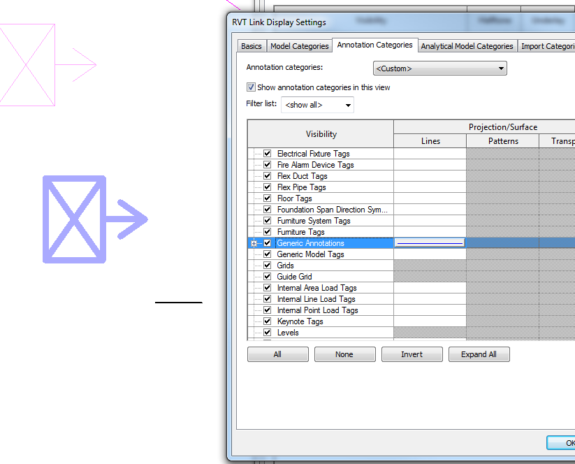
Oh wait, you can’t… put more simply, you cannot override the lineweight of Generic Annotations for a linked file. In fact, it turns out you can’t override lineweights for anything, including Model elements in a linked file… you are stuck with them. You can Transfer Project Standards into the link but that is a painful workaround.

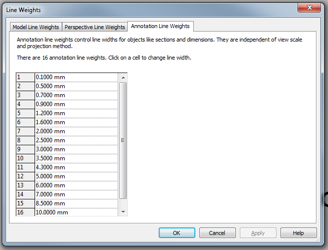
You can override the colour and linetype, no problem. But no matter what you try: Object Styles, Visibility Graphics, Revit Link Visibility overrides, none of this overrides the actual Lineweight of Generic Annotations in the linked file. It is using the value from the Line Weight settings, Annotation Line Weights tab IN THE LINKED file to draw these items in the host file. If Pen 1 is set to 0.3mm in the Link, you will never be able to get a lighter pen weight override in the Host.

To me, this is a bug. If the Revit Link visibility is set to Object Styles – By Host File, annotation line weights should be overriden to match the applied pens.

Unfortunately, this is not the case. Here is a video showing the problem:

Upon further investigation, nested Annotations in Component families that live in a Linked File can’t really be overridden by Visibility/Graphics, unless you edit the Revit Link visibility. Even then, you can set line weights and colours but they will still reference the Linked File Annotation Line Weights.

Fairly nasty stuff, particularly if you are working with linked files from consultants / contractors that extensively use nested Generic Annotations inside their families (sidenote: I’m pretty sure this always a bad idea. Model in 3D, use tags for text, if you have to have text in the family use Model Lines or Model Text or some other method so that you don’t have nested Generic Annotations. They scale wildly around and become a crutch for not modelling in real world scale).

Ok, so we have a problem. I discovered that there is one master switch that works in the Host file to get around this.

1) Set the Family Category to Halftone, this will override the linked, nested Generic Annotation

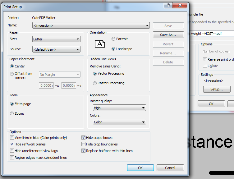
2) When printing, tick the “Replace halftone with thin lines” box in Print Setup

I realise that this is not WYSIWYG, and I really don’t like that. But it does work. Here is a video:

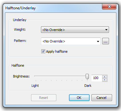
But wait, there’s more. We can actually make it closer to WYSIWYG (is that a thing?), if we adjust the Manage – Additional Settings – Halftone/Underlay to 100. The lineweight will still display incorrectly, but it will print correctly, and there will be no halftone effect.

Some further reading:
Linked File Line Weights – The Revit Clinic

Evox Linkator will give you access to a new toolbar that contains all the commands necessary to create links to web sites or files from your PC.
Everything is possible through two simple buttons with which you can connect the elements or the whole family to a Web site, to data sheets in PDF, dwg of detail and everything you need to integrate your project.
From Manager you will be able to monitor all links anytime, in order to control those to be repaired or to eliminate unnecessary ones.

Download at:
eVox Linkator TRIAL | Autodesk Revit | Autodesk Exchange Apps

These are part of the Standard, Free BIM Project Suite by CTC:

BIM List is a content management solution providing the ability to sort, search and leverage your families more effectively.
  • Locate and insert families into a Revit project
  • Search parameter data using filters
  • Administrative controls help enforce company standards


Detail Link automates the process of linking AutoCAD DWG details for use in the Revit project environment.
  • Reduce errors and ensure consistency
  • Save time by automating an otherwise manual process


Project Link is an easy and customizable system for finding and organizing documents from inside the Revit interface.
  • Make important documents and hyperlinks accessible from within Revit
  • Locate and group all families that have a hyperlink associated with them
  • Both administrative and user interfaces are provided


Renumbering provides a fast and simple way to renumber your rooms and doors.
  • Auto-swapping avoids duplicates
  • Alphanumeric sequential numbering
  • Add separators and suffixes to room and door numbers

Download at:
BIM Project Suite Standard

Heads-up:
Revit Add-Ons: BIM Project Suite 2014 from CTC – Includes 4 New Tools!

Have you created a heap of wall based families that you would like convert to face based?  Jarod Schultz provides a nice workaround for this.  Essentially, you Link and then Copy/Monitor the elements, then when you use the Edit Family button, Revit swaps them to Face based for you!

“Get into a 3D view so it is easier to see your linked file and the lighting fixture. We are now going to use the “Copy/Monitor -> Select Link” tool to “Copy” in the light fixture.”

Read the whole post at:
Jarod Schultz: Revit Wall/Face Based Family Trick | Jarod Schultz

EDIT

This workflow can be used to convert any hosted Family to a Workplane based or unhosted versions, as David describes here:

  1. Place an instance of the family you want to hack in the drawing area. You can insert multiple ones at the same time;
  2. Save the file and close it;
  3. Open a new Revit file from no template. This ensures it is completely empty and Revit will thus create this hacked copy when we do step #6;
  4. Link the previously saved model into this new file;
  5. Go to the Collaborate Tab>Copy/Monitor>Select Link and pick the linked file. Once in C/M mode, click Coordination Settings and make sure that the family types you want to hack are set to “Copy Type”;
  6. Click the Copy button and pick the families you want to hack;
  7. Finish and exit from this mode when you’re done.

Posted by Mark Petrucci:

  •  Did you know there is another point called the Startup Location? Be default, the PBP and SP are located on top of the Startup Location. What is the Startup Location used for? It’s used for linking models ORIGIN-TO-ORIGIN.
  • If you are an engineer and want to link the Architect’s project file origin-to-origin, you need to do this before you start the engineering model.
  • if a structural engineer lays out column grids without the architects model and then links files later, origin-to-origin will not work.
  • never, I repeat never move the building. I’ve read blogs on how to move a building using infinite view ranges. This does not work…

via
Applied Software Blog: Revit Shared Origin Survey Startup Base Location…

“In Revit, the default font is Arial, for example, is therefore the DWG file represent fonts in Arial.
The “shxfontmap.txt” is located at:
C: Users AppData Roaming Autodesk Revit Autodesk Revit 2013
First you should make a backup copy of “shxfontmap.txt” are created, they can then be opened with Notepad.
Note: Please do not use software to edit the file, which could change the formatting of text, such as Word.

At the end of the file is then added to “txt.shx Arial” or “Arial italic8.shx” added.

After the names of the SHX once is “Tab” and then use the new font specified.”

via
Google Translate
of
Autodesk BIM Blog – Darstellung von SHX Schriften f�r DWG Dateien anpassen – Revit Architecture/MEP/Structure 2013

Interesting message when linking a Group to a new RVT file… basically, if you have a Model Group in your project that has Excluded Elements (either deliberately or due to some unavoidable issue) and you then Link that Group, the excluded elements will be restored in the Link.

Excluded elements are also restored for Attached Detail Groups if you choose to link them as views, but you won’t get the nice little message.

This could be one way of recovering the excluded data without having to create a new instance or use the ‘Restore All Excluded’ command on an existing instance…

Steve made a few interesting points today about Revit and DWG (Import) extents.  I previously posted about Revit accuracy and precision here.

However, did you notice this new setting when importing a DWG in Revit 2013?

If you UNtick the box that says Correct lines that are slightly off axis, then Revit 2013 will bring in the DWG as-is.  It won’t try to straighten things up to make the DWG more Revit-friendly.

Obviously, use this with care.  But for me, 9 times out of 10 I want the DWG to come in EXACTLY as it was drawn.

Oftentimes, you will want to flatten a DWG file before bringing it into Revit, so that Revit isn’t confused by all the Z-values… you can use FLATSHOT or the DXB plotter methods, as described below:

Issue
You want to create a flattened two-dimensional (2D) drawing of a three-dimensional (3D) model.

Solution
If you are using AutoCAD 2007 and higher, the FLATSHOT command is available to convert 3D solids to flattened 2D views. (Note this command is not available in AutoCAD LT.)

The other method to create a 2D drawing from a 3D model is to:

  1. Configure a DXB plotter using the Add-A-Plotter wizard

Read the rest at:
Autodesk – AutoCAD Services & Support – Flatten 3D model to 2D