Over at Virtual Built Technology, we have an aspirational view of our industry – that together, we can arrive at a set of best practice workflows for BIM and VDC projects.

We have been developing and refining our own set of internal workflows for a number of years, and today we would like to start sharing those with the world.

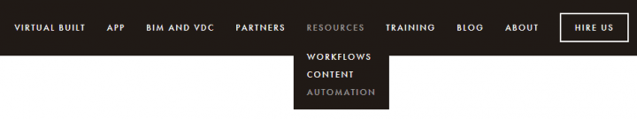
We will periodically post best practice workflows in the Resources menu on our site.

bim and vdc resources

From here you can browse to various resource types, including:

  • Workflows – for workflow documents and flow charts
  • Content – for BIM files like Revit templates and families
  • Automation – for scripts, like Dynamo graphs

The individual resource pages are also fully Disqus comment enabled, so you can start a conversation there. Let us know if you think we are on the right track… or not 🙂

Already, you will find our How to Use a Revit Control File guide, and a script that will automatically create section-boxed 3D views from a Revit Control File.

Also, from anywhere on our website you can immediately contact us using the Intercom badge at the bottom right of the screen – it looks like this:

Click on it anytime and let us know if you have any questions or suggestions, or would like assistance with your BIM and VDC projects.

We look forward to engaging with you soon!


Some good tips on using the Revit Project Browser “Arrange By” setting in the Object Organizer in Showcase to make things a bit easier to manage…

PDF download link:
http://dccadd.com/bldg/wp-content/uploads/2012/10/Building-Design-Suite-Workflows-Revit-to-Showcase.pdf

via
Building Design Suite Workflows – Revit to Showcase | Building Solutions

Heads-up: Belinda Thompson

Aaron Maller has been travelling a lot lately, but he still found the time to upload some of the recent presentations that he has delivered:


Flicking through the Glasgow RUG PDF, you will find cool stuff like:
 
 
I also like these words from his post:

Its really not enough to be doing the best that i can in one country.

We need a vehicle, for reaching a Global platform.

i dont post these thinking they are anything more than what they are:  One small groups workflow that happens to get us through some specific needs.

Read more / via:
Malleristic Revitation: Malleristic BIM travels

I saw some information on this Project a while back – it looked very cool indeed.  Essentially it allows you to record and replay a tutorial or workflow in extreme detail.  For Autodesk products, it may likely replace tools like Camstudio, Hypercam, Screencast and SnagIt.

(embedded JWPlayer)

There are already a stack of tutorials uploaded at https://chronicle.autodesk.com/

From the Labs site:
Project Chronicle is a free technology preview from Autodesk Research that makes it extremely convenient and easy for users to capture, share, and learn from software workflows. Project Chronicle consists of a recording utility to capture recordings, and a website that displays the recordings as Chronicles, interactive video tutorials.
The Chronicle Recording Utility allows users to capture workflows from within Autodesk products. The utility records a continuous video screen capture and optionally voice narration. What makes Chronicle unique is that is also records the timing and details of workflow information, such as the tools, settings, and dialog boxes that are used during the workflow.
Captured data is then uploaded to the Chronicle Website where other users can view a video of the workflow. Additionally, the captured workflow events are displayed on an interactive timeline, enhancing the viewing and learning experience.
In essence, Project Chronicle will allow software experts to showcase their expertise and will allow other users to view and learn from their real-world expert examples.
Please visit the Project Chronicle Website: https://chronicle.autodesk.com.

via
Autodesk Labs Project Chronicle

Some other info:

Paper
Chronicle: Capture, Exploration, and Playback of Document Workflow Histories

Tovi Grossman, Justin Matejka & George Fitzmaurice. (2010).
Chronicle: Capture, Exploration, and Playback of Document Workflow Histories
UIST 2010 Conference Proceedings:
ACM Symposium on User Interface Software & Technology.
pp. 143 – 152.

CATIA (Computer Aided Three-dimensional Interactive Application) is a multi-platform CAD/CAM/CAE commercial software suite developed by the French company Dassault Systemes.


Commonly referred to as a 3D Product Lifecycle Management software suite, CATIA supports multiple stages of product development (CAx), from conceptualization, design (CAD), manufacturing (CAM), and engineering (CAE). CATIA facilitates collaborative engineering across disciplines, including surfacing & shape design, mechanical engineering, equipment and systems engineering.

So, how do we go from CATIA to Revit / 3dsMax?

A couple of videos for this workflow were recently posted to Rethinking BIM here.  One method seems to go Catia to IGS to Rhino to SAT to Revit.  Embedded below:

I’ll admit it – I’m a bit excited about MeshMixer.  I downloaded it today and was very pleased at how easy it is to sculpt things.  A few years back, we worked on an aquarium project with another architect, and it was suggested that it would be great if Revit could generate freeform rock formations that looked realistic.  At the time, I played with Blender and a little add-on called ‘Blender World Forge’.

However, I think MeshMixer can also do the job.  After installing the program I was very surprised that it is actually called Autodesk meshmixer – anyone tell me what is going on here?

Anyway, to see me create some organic-looking rocks and bring them into Revit, check out the video:

Basically, this was my workflow:

  1. Install MeshMixer
  2. Open it, grab a Sphere, do some sculpting.
    (EDIT: You can probably skip steps 3,4 and 6 if you use the built-in Export feature on the File menu… let me know if it works for you.)
  3. Create a part out of the sculpted form you made
  4. Save the project, and find the part OBJ file at
    C:UsersusernameDocumentsmeshmixerlibrariesdefault
  5. Import that into 3D Max
  6. Cap the holes in the mesh
  7. Export to SAT
  8. Import into Revit family, adjust materials.
  9. Load into Project.

Here is the download link again:
MeshMixer

Heads-up via http://labs.blogs.com/its_alive_in_the_lab/2012/03/software-makes-me-look-20-years-younger.html

Revit doesn’t want you to copy lines between Annotation and Model Families (see below)

However, it can be done. This is the workflow to copy lines from Annotation to Model families:
  1. Copy lines from the Annotation Family to a plan view in a Project File.
  2. Copy the lines from the Project File to a Profile Family.
  3. Copy the lines from a Profile Family to the Model Family.


Pretty tricky workaround huh?

Have you ever wanted to ‘re-issue’ or revise a large group of sheets such that they all receive the same, updated revision in the Revision Schedule?

Lets say you have 100 sheets and these form the ‘Approval’ set of documents – how do you go about amending and reissuing them?

For significant revisions, it is our company policy that all revised sheets have the same entry in the Revision Schedule. Therefore, we use the following method (it takes a little setting up the first time, but it is worth it):

  1. On the first sheet you would like to re-issue, create a small section of Revision Cloud that is associated with the appropriate revision in from the Sheet Issues/Revision dialog box.
  2. Select this small section of Revision Cloud and Group it into a detail group. Call this group whatever you like – something like ‘Approval Revision Set 1’
  3. Select the Detail Group and Ctrl-C (copy to Clipboard)
  4. (At this point we usually Hide the Revisions from the sheet by Tab-selecting the Revision Cloud and Hide Category in View, as we don’t really use Revision Clouds in the traditional sense)
  5. Go to the next sheet in the set and Paste-Aligned
  6. Repeat this for each sheet you would like in the ‘Revision Set’ (you will notice that as you do this, a new entry appears in the Revision Schedule – as you would expect)

Now, you can quickly re-issue that entire set. How?Just edit the ‘Approval Revision Set 1’ Detail Group that you created, and:

  • Add a new piece of Revision Cloud that is associated to the appropriate entry in the Revision Schedule. All your sheets have now been issued with the new entry, and the Revision Schedule on each sheet shows the new entry!

You can do some tricky things with ‘nesting’ these Detail Groups to give you more flexibility or add new sheets to sets.

Many Revit users will encourage you to convert your AutoCAD details into Revit details.

However, perhaps this isn’t a valid option for you (due to time constraints). You can find some good information on how to successfully link the AutoCAD details into Revit (some links below). In addition to these, I have found the following to be successful:

  1. In the Revit project, set up lineweights for you detail scale levels (1:5, 1:10 or similar) to equate to the lineweights you would use in AutoCAD.
  2. Setup your ‘Import Line Weights’ (Ribbon – Insert tab, Import panel, little ‘arrow’ for settings). Basically, this maps your AutoCAD colours to Revit lineweights.
  3. In the AutoCAD detail, use Multileaders if possible. In our case, this wasn’t an option (as Multileaders simply didn’t give enough graphic control for one of our architects). If you can’t use Multileaders, explode all MTEXT to DTEXT (this fixes problems with the MTEXT not wrapping correctly in Revit. If you need to come back and edit the text in AutoCAD, then use the Express Tool to convert the DTEXT back into MTEXT before editing. Convert all QLEADERS and LEADERS to MLEADERS with blank text boxes. The arrows didn’t work for us using LEADERS, but MLEADERS showed up fine in Revit. I did this manually – I set up a MLEADER style that didn’t have a landing or text, and then traced over the LEADER objects. I then deleted the original leader objects. So I was left with DTEXT and blank MLEADERS – this displays perfectly in Revit.
  4. Set up your detail DWG files such that there is ONE detail per DWG.
  5. Link into AutoCAD drafting views using ‘black and white’ for colours (the Import Line Weights takes care of the lineweight settings).
  6. In each drafting view, if you need greyscale or colour layers to be linked from AutoCAD, use the Revit Visibility/Graphics to override those layers to the original colour. (You could also do this in reverse – link layers with original colour, and override black layers to black…)

These were just a few things that made this process work for me. I encourage you to check out these links:http://forums.augi.com/showpost.php?p=829155&postcount=6Maximum number of linked files?Using AutoCAD details Best Practices

Autodesk Impression 3 has been readily available for some time now. But would you like to know how to turn your Revit drawings into ‘sketchy’ looking plans?

Its simple:
1) Install Autodesk Impression 3 from Subscription (or the trial from here)

2) Open your Revit project, and open the view that you want to make ‘sketchy’

3) Export the view to a DWG file. Ensure that it is a ‘single’ DWG – untick the ‘Xref views on sheets’

4) Open AutoCAD and open the file you just exported.

Now, we want to make a CTB from the PCP, so do the following:

5) In AutoCAD, type ‘STYLESMANAGER’ – this opens the location for all your CTB files.

6) Double click the ‘Add-A-Plot Style Table Wizard’ shortcut

7) Select ‘Use a PCP or PC2 file’ and hit Next 
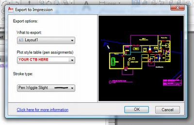
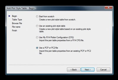
8) Select ‘Color-Dependent Plot Style Table’9) Browse for the PCP that Revit automatically created when you exported the DWG earlier and hit ‘Next’

10) Choose a filename for the new CTB file that you have createdOkay, now we go back to AutoCAD and export Impression. I found that the scaling was simpler direct from AutoCAD, rather than trying to put the DWG file straight into Impression.

11) In AutoCAD, you should still have the file open that you exported. Now, type ‘IMPRESSION’ and hit Enter.12) Under ‘What to Export’, choose ‘Layout1’
13) Choose your CTB under ‘Plot style table’14) I like the ‘Pen Wiggle Slight’ for ‘Stroke type’15) Hit ‘OK’ – Autodesk Impression will now open, and your file will look sketchy!!16) You could do more work in Impression, or you could just hit ‘File – Save As…’17) Choose PDF (if that’s what you like), then under Resolution, choose ‘Custom’ and type 300 dpi if you want decent quality. Type your File Name and hit OK.There you go! It seems like a lot of steps, but once you have done it a couple of times, you will very quickly be able to convert your Revit floor plans into sketchy drawings for presentation!These can be very useful early in the design process – if your drawings look ‘sketchy’, the Client may feel like you haven’t resolved everything without consulting them. Therefore, the Client may feel that you care more about them and their ideas.

Check out this link for some examples.