HyunWoo Kim has been posting some very interesting stuff over the last couple to his English-language blog, Enjoy Revit.  The content of his blog is quite interesting to me – including adaptive component rigs, solving documentation problems, and dealing with family and content creation issues.

2 point and 3 point Circle Adaptive rigs
with formulas, and this arch family for download

Symbol Annotation as 3pt Adaptive for sections
download

A very curved automatic Adaptive Stair
download

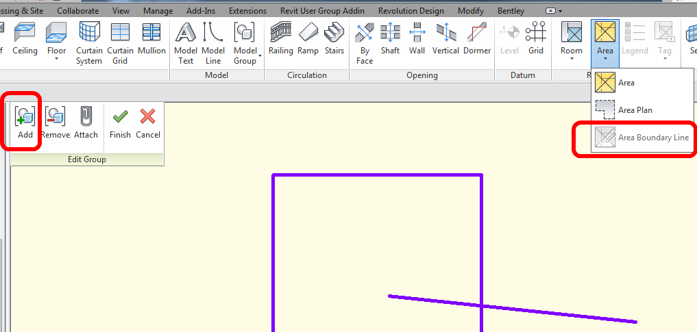
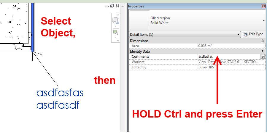
Workaround to enable the “Show Only if Instance is Cut” option for Symbolic lines
(ie. switch to Structural Framing and back again)

Curved Insulation Family
download (quite a lot of work in this)

The hidden edge trick in 3dsMax for Sketchup import to Revit
I posted about this here

His Korean site is at Enjoy Revit : 네이버 블로그 .  He also has a Google Site at:
Enjoy Revit.

He is quite prolific on Youtube too – his channel (in English) is:
HyunWoo Kim – YouTube

EDIT2: new version (January 2014) at
Code: codice sorgente

Compiled  DLL and ADDIN
(copy to C:ProgramDataAutodeskRevitAddins2014 and Unblock the DLL)

via
http://puntorevit.blogspot.it/2014/01/view-depth-override-polar-distance_8.html

EDIT1: The code is at
Punto Revit: View Depth Override – Codice Sorgente

Paolo has created a macro that overrides elements based on their distance from the viewpoint.  Check out the video:

On his blog, he offers to share the code, if you ask 🙂

via
Google Translate
of
Revit Point: View Depth Override

When in Edit Mode for a Model group, the Area Boundary Line tool is grayed out.

However, to work around this limitation, you can:

  • Select Area Boundary lines that exist ‘in the project’ and then trigger the Group command to group them, or
  • Edit an existing Model Group and use the ‘Add’ option to bring Area Boundary lines from the Project into the Group

It is an unusual limitation, but the above workarounds are not too onerous.

As you may have realised, you cannot add the Area parameter to a Floor Tag annotation.

Here is a workaround:

  1. Make a Floor Schedule with Area and Comments fields added.
  2. Filter By – Comments = the Comments of the Floor you want to tag (this needs to be a unique entry).
  3. Turn off Headers, Grids etc in the Schedule Appearance.
  4. Hide the Comments field in the Schedule.
  5. Rename the Schedule to something like:
    Floor TAG – Deck Area
  6. Drag and drop this Schedule a.k.a. Tag onto a Sheet, on top of the Floor in question.

OK, I understand that this is not the most manageable or elegant solution, but it may be useful in certain situations.

Do you get annoyed by the warning:

Can’t create duplicates in Edit Group mode.

If you are editing a group, and want to make a Duplicate of something, simply scroll to the item in the
Project Browser – right-click – Duplicate.

EDIT (added 5 Dec 2011):

In other words, this tip allows you to create a new Family Type in Edit Group mode. You may get annoyed when you aren’t allowed to make new Family Types when you are in Edit Group mode and Revit just keeps telling you:
Can’t create duplicates in Edit Group mode.

Just use the Project Browser instead – scroll down to the family in question, right click on a Type and Duplicate.  Revit will let you do this, even while in Edit Group mode.

When in Edit Mode for a given Detail Group, the Spot Dimension tools are grayed out.

However, if you place the Spot Dimension OUTSIDE the Detail Group, and then ‘Add’ it to the Group – Revit is quite happy.  You can even place a Spot Coordinate in a Detail Group (in Plan View), copy the Group instance, and then drag the copied Group around with the Spot Coordinate continuously updating!

Here is a quick step-by-step:

  1. Exit the editing mode for the Detail Group
  2. Place the Spot Dimension (referencing an element inside the Detail Group)
  3. Edit the Group
  4. Use the ‘Add’ tool to add the Spot Dimension to the Detail Group
  5. Finish Group

 This works for Spot Coordinates in Plan View Detail Groups, and it works for Spot Elevations and Spot Slopes in Section / Elevation Detail Groups…

    Many people know that you can add a carriage return (and thus create multi-line labels) in Revit by accessing a Properties entry box and hitting Ctrl+Enter:

    Over at Revitez, another method was mentioned – namely, copy multiline text from Notepad into a Properties parameter box.  This works well – and you can navigate between the lines in Revit using Up and Down arrow keys.

    Finally, you can accomplish essentially the same thing by holding Alt + typing 0010 (then release Alt).  This will also insert a well behaved carriage return into the parameter.

    Some ideas via Revitez!:
    Google Translate
    In French http://revitez.blogspot.com/2011/07/texte-multi-ligne-dans-un-libelle.html

    Here is slightly nasty, anti-BIM trick: 

    If you are trying to override a dimension in Revit with a different dimension, it can be a pain.  Yes, you can mess with the ’rounding’ to try and get it right, or you can override with a decimal point, but what if you just want to show something that is totally different to the actual dimension without having a little dot floating around?

    1. Open up the ‘Character Map’ (Start – Accessories – System Tools – Character Map).  
    2. Scroll down until you see a bunch of blank boxes
    3. Copy one of the blank characters using the buttons at the bottom of the dialog.

    4. Go to Revit.
    5. Double click on the dimension you want to change.
    6. Paste the white space character into the ‘Replace with text’ box.
    7. Type the dimension you want in the ‘Above:’ part
    8. Drag the dimension into the correct location.

    Like I said, this isn’t really ‘Best Practice’.  Use this workaround with care!

    I came across a slightly unusual issue today.  I was trying to place a simple Spot Elevation on a Topography surface in a Detail View that originated from a Plan view.  But it wouldn’t work!!

    However, if you place the Spot Elevation in a normal Floor Plan view, you can then copy and ‘Paste Aligned’ into the Detail View.

    The brief video below demonstrates this process: