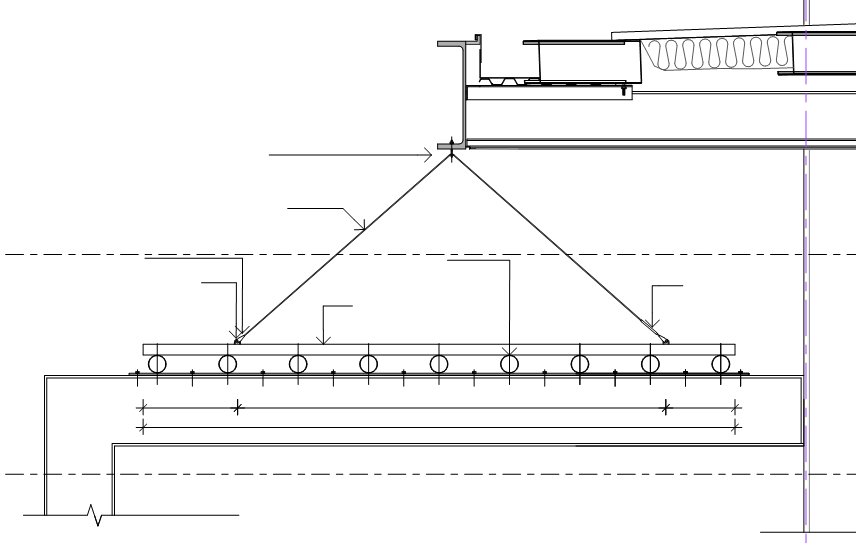
I printed a PDF from Revit today, and was presented with this output:

The text was not printed from a linked DWG.

This problem resulted because:

  1. I linked a DWG into a Detail (Section) View
  2. I then rotated the Detail View in Plan.
  3. I moved the linked DWG back into position.
  4. But obviously Revit was not impressed with this course of events!

It was a relatively simple fix – I used Ctrl-X to ‘cut’ the DWG into nowhere, then pasted it back into the view, and also ‘reloaded’ the DWG from the Manage Links dialog.

Many Revit users will encourage you to convert your AutoCAD details into Revit details.

However, perhaps this isn’t a valid option for you (due to time constraints). You can find some good information on how to successfully link the AutoCAD details into Revit (some links below). In addition to these, I have found the following to be successful:

  1. In the Revit project, set up lineweights for you detail scale levels (1:5, 1:10 or similar) to equate to the lineweights you would use in AutoCAD.
  2. Setup your ‘Import Line Weights’ (Ribbon – Insert tab, Import panel, little ‘arrow’ for settings). Basically, this maps your AutoCAD colours to Revit lineweights.
  3. In the AutoCAD detail, use Multileaders if possible. In our case, this wasn’t an option (as Multileaders simply didn’t give enough graphic control for one of our architects). If you can’t use Multileaders, explode all MTEXT to DTEXT (this fixes problems with the MTEXT not wrapping correctly in Revit. If you need to come back and edit the text in AutoCAD, then use the Express Tool to convert the DTEXT back into MTEXT before editing. Convert all QLEADERS and LEADERS to MLEADERS with blank text boxes. The arrows didn’t work for us using LEADERS, but MLEADERS showed up fine in Revit. I did this manually – I set up a MLEADER style that didn’t have a landing or text, and then traced over the LEADER objects. I then deleted the original leader objects. So I was left with DTEXT and blank MLEADERS – this displays perfectly in Revit.
  4. Set up your detail DWG files such that there is ONE detail per DWG.
  5. Link into AutoCAD drafting views using ‘black and white’ for colours (the Import Line Weights takes care of the lineweight settings).
  6. In each drafting view, if you need greyscale or colour layers to be linked from AutoCAD, use the Revit Visibility/Graphics to override those layers to the original colour. (You could also do this in reverse – link layers with original colour, and override black layers to black…)

These were just a few things that made this process work for me. I encourage you to check out these links:http://forums.augi.com/showpost.php?p=829155&postcount=6Maximum number of linked files?Using AutoCAD details Best Practices