I hope that you found my previous post on batch printing with automatic naming helpful.
But what if you want to add a prefix or a suffix to all PDFs in a set? Some firms like to add the current revision or issue date as a suffix to each individual sheet. This can be accomplished easily with the freeware program Advanced Renamer. It is available in both portable and installable versions.
Here is a few simple steps to add a suffix to all PDFs in a specified directory:
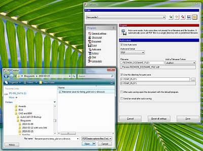
- Install and run Advanced Renamer.
- Click Add – Directory. Select Directory and click OK.
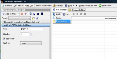
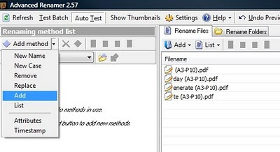
- Click Add method – Add (this will obviously ‘add’ something to the filename of resulting files.)

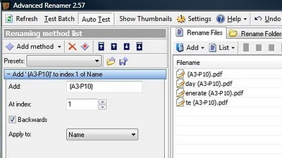
- Set the options for the Add method: Type the text you would like to add, select index 1, ‘backwards’ and Apply to Name. This will add the specified text to the end of all filenames in the directory.
- Click ‘Start Batch’ and you are done.
You can experiment with other ‘methods’ to do some more advanced renaming tasks.