At various points in a BIM project, Revit models may get passed from one consultant or contractor to the next. After this handover occurs, a change in project requirements may mean that the recommended modelling practice has now slightly shifted. For example, in healthcare and hospital projects, host and nested Revit family arrangements are often used to control repeating layouts, such as in wet areas and other typical rooms.

Often, many of these nested fixture families are also Shared families, meaning they can be scheduled and accurately counted in Revit schedules.

However, what if a contractor needs access to some of these nested families in their own model? For example, what if a plumbing contractor wants to copy all nested plumbing fixtures into their own model, perhaps to add parameters or generate maintenance schedules for FM?

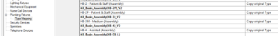
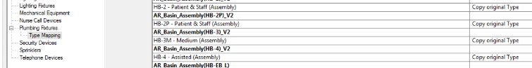
There are a few different ways to go here, with varying degrees of hackiness and/or gracefulness. An extremely hacky way to go might be to export IFC, open IFC to get each of these nested families as their own instances. Or, you could use Copy/Monitor. When using Batch Copy, each family gets emancipated from its original host family. It certainly should be used with care, as some things don’t work especially well… Like instance parameters aren’t really copied across, and you may end up with some duplicated elements. But for the most part, as a built-in Revit solution, it can do a decent job. I put together a brief workflow on how you might go about this process, and you can download it here.

As usual, test the workflow thoroughly before implementing it, and use at your own risk.

Oh, I wanted to mention yet another way this could be done… with Dynamo. I recently developed a solution that can free nested families for an entire rvt at once, including:

  • create new instances of all nested families of a desired category in correct locations
  • set original element IDs to original and new instances
  • set a parameter to determine if an element was ‘original’ or newly created by the script
  • rotate instances to match original
  • mirror or flip if necessary
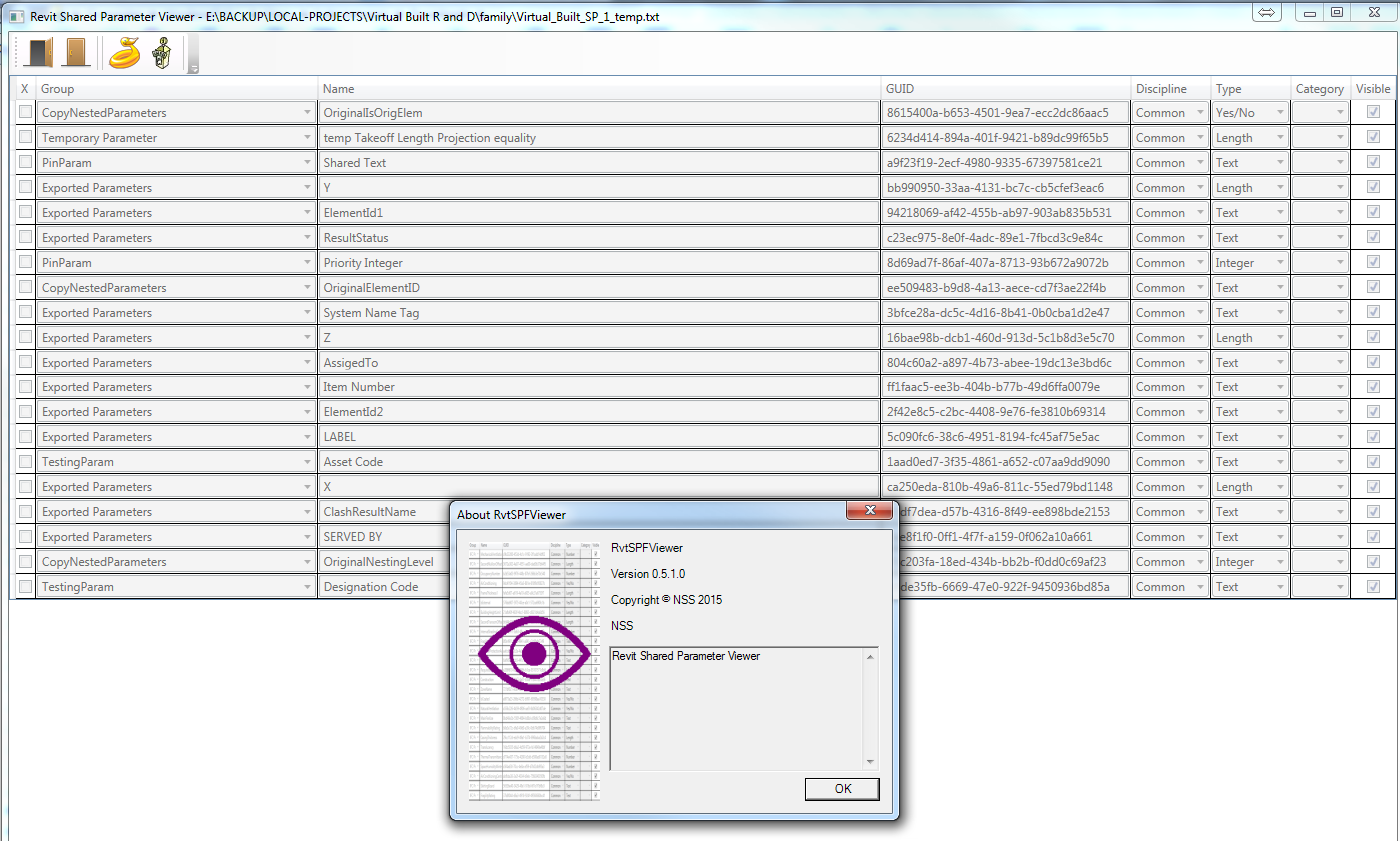
  • copy all parameters from original elements to new instances
  • select top level elements for deletion

But that’s a subject for another post… 🙂

If you are having trouble getting a particular NWC uploaded to Glue, here are some steps to try:

  • you can open it in Navisworks, export to DWF and try Uploading that using the Glue client
  • you could open it in Navisworks 2015 and then Glue It from there. Unfortunately, there is no ‘Glue It’ addin available for Navisworks 2016. As I understand it, the new Glue sync features in 2016 mean that a simple Glue It button for Navisworks will not be available in Navisworks 2016.

Also, there are new addins available today (11 May 2015):

Go to this link to download BIM360 addins (you will need to sign in to Glue first, then use the link below):
https://b2.autodesk.com/downloads/unknown

More at: To Install BIM 360 Add-Ins | BIM 360 Glue | Autodesk Knowledge Network

From microsolresources:
Select your project, and you will get a list of cloud-enabled models. Please note you will not see other data, such as Word documents or non-cloud enabled models. capture9-1972819

When you click on the icon that resembles a floppy drive, you will have an option to View Versions.

capture11-5805882

Each of these Versions refers to an instance of Sync to Central.

On the far right column, we see Actions. If you click on the clock icon, you can roll back to a previous STC. You should exercise caution whenever rolling back to an earlier version. ALL NEWER VERSIONS WILL BE DELETED WHEN YOU ROLL BACK. In addition, anyone currently working on that model will lose their work, and any changes will be orphaned.

Read the whole post at:
Backing Up A360 Collaboration for Revit Models | microsolresources

Spiderinnet has posted a free shared parameter file viewer (download).

  1. Extract the zip
  2. Run RvtSPFViewer.exe
  3. Click the open door and select your Shared Parameter file

“… help view Revit shared parameters in a nice window, we created the Revit Shared Parameter Viewer (RvtSPFViewer.exe).
SampleUI

It can be downloaded below.
Revit Shared Parameter Organizer”

Original post:
Revit Shared Parameter Viewer – RevitNetAddinWizard & NavisworksNetAddinWizard

Let’s say you want to tag Duct Accessories in a linked Revit model. That’s easy, because Revit can Tag All… Linked Elements by Category. Just tick the box in the dialog below:

But what if you only want to Tag certain Duct Accessories, like those that actually have a value in a given parameter? What we need to do is limit the view to only showing what you want to tag, and then run the Tag All Not Tagged command as above.

Here’s how:

  1. Duplicate the view you are working in
  2. Hide all unnecessary Links
  3. Use View Filters to hide the elements you don’t need, by using the parameter you actually want, something like this:
  4. After you have hidden off these elements, run the Tag All command in this view
  5. Select all of those new tags (right-click on one of them, Select All Instances – Visible in View)
  6. Copy
  7. Switch back to the original view and Paste Aligned to Current View

So What does Revit Want? For you to think about how it works, and then use it accordingly. In this case, we realised “hey, Revit tags only what it sees…” Then, we can develop the workflow above to solve the problem.

    Simon Moreau has shared a nice addin for Navisworks that allows the automatic grouping of clashes. From his blog:
    “This plug-in enables a lot of possibilities for sorting clash detection results in a meaningful report, and will become a full-time member of my coordination toolbox.

    To install this plug-in, you can copy-paste the ClashDetective.ADSK.dll file available here in a new ClashDetective.ADSK folder in C:Program FilesAutodeskNavisworks Manage 2016Plugins. You can also see my edited version of the example code here.”

    Original post: Grouping clash results | BIM 42
    Heads-up from Michael Clothier

    Here is what the installation folder looks like:

    And the addin ribbon in Navisworks Manage 2016:

    You can also download the Navisworks SDK from here:

      Navisworks 2016 SDK (Updated April 7th) (exe – 207 Mb)
      Navisworks 2015 SDK (Updated July 1st) (exe – 193 Mb)
      Navisworks 2014 SDK (exe – 217 Mb)

    How to use:

    1. Install the update to AutoCAD 2016
    2. Open a DWG file
    3. CMATTACH
    4.  Choose NWC or NWD to Attach (this lets you view the Navisworks file in your AutoCAD drawing).
    5. Untick Insertion point (so it uses 0,0,0) and tick Show current drawing geometry
    6. Switch your VISUALSTYLE to Realistic
    7. Confirm CMOSNAP is set to 1
    8. Try using measure or make a dimension
    9. Try modelling – you can snap to geometry in the attached NWD / NWC file. One of the easiest things to draw is a 3DPOLY (3d polyline). It will snap freely to vertexes in your model.
    10. You may have to do a ‘refresher’ course on UCS in AutoCAD, but one easy way to quickly start modelling is switch to a view using ViewCube (such as Right), then type UCS, then type V for View. You can now model on the plane of these view to make new AutoCAD geometry.

    Info:
     This Feature Update provides a way to specify precise locations on an attached coordination model using the standard 2D endpoint and center object snaps. If Endpoint or Center are set as running object snaps, a marker and a tooltip display when you move the cursor over these locations on an attached coordination model.
    You can also use these object snaps any time you are prompted for a location and you want to specify a precise location on an attached coordination model. Hold down Shift and right-click in the drawing area to display the Object Snap shortcut menu. Select Endpoint or Center to snap to precise locations on the attached coordination model.

    The following system variable has been added.
    CMOSNAP (System Variable)
    Controls object snapping for coordination models.

    Type: Integer
    Saved in: Registry
    Initial value: 1

    0 – Object snapping is disabled for geometry in all coordination model attachments in the drawing.
    1 – Object snapping is enabled for geometry in all coordination model attachments in the drawing.

    Readme

    Direct link:
    http://download.autodesk.com/SWDLDDLM/Updates/AutoCAD/2016/AutoCAD_2016_CM_Osnap_Support_x64.exe