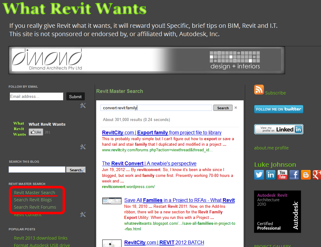
I have created a new custom search engine that searches through hundreds of Revit blogs and the main Revit forums at:
Revit Master Search
I have also updated the Revit Blog Search and Revit Forum Search pages.
AI Empowered Project Management
I have created a new custom search engine that searches through hundreds of Revit blogs and the main Revit forums at:
Revit Master Search
I have also updated the Revit Blog Search and Revit Forum Search pages.
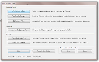
WhiteFeet Tools for Revit is a powerful set of add-ins that can make the impossible, possible. I have posted about them before. In this brief post, we look at how you can effectively Schedule the Reference Planes you have in a model.
On the Add-ins Ribbon, choose Utility Tools – Schedule Tools:
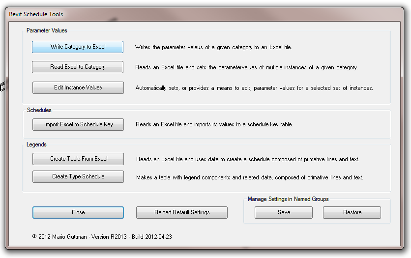
Pick Write Category to Excel, then select the Reference Plane category, All Elements in Model:
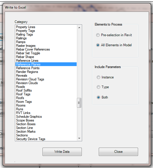
After you press Write Data, you will get something like this:
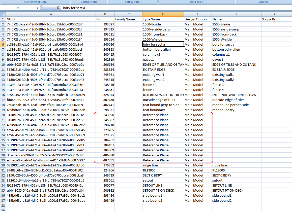
You can then sort the Data to find the unnamed versions, and then use the Element ID to select and name those Reference Planes, if you so desire. In our office, an unnamed Reference Plane is fair game for deletion…
Also, some of you may have picked up that you can use this same process to export data from ANY CATEGORY in Revit – including those that you cannot schedule!
Find out how to obtain the Whitefeet software here:
Tools

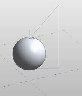
(dissolve it if you want to see how it works)
In response to:
Oh, why is it impossible to make seamless spheres in the #Revit conceptual massing environment? Why?! Time for beer.
— Sean David Burke (@seandburke) February 23, 2013
Collaboration is the buzzword in the AEC community for 2013. Something relatively unique to the current era of technology is Architectural collaboration – more than one firm of Architects working on a single project.
But how do we collaborate across large geographic distances? And how do Architectural collaborators (we are not talking about consultants here) handle modelling standards and model management in general?
There is so much rhetoric out there, both from a technological and a psychological perspective. There are a plethora of cloud-implemented technologies, including Revit Server and VEO. There are a bunch of different theories about the best way to control the entire process.
So, what is your firm doing to solve these problems?
Consider a few thoughts from this case study posted in August 2012, co-authored by Cara Gastonguay, Associate AIA LEED AP, Payette and Carolyn Hoef, Associate AIA LEED BD+C, Ayers Saint Gross.
Different firms have varying electronic standards, and templates and conventions. In the BIM world this also means varying project file templates, families, detail components and even line styles. Choose one team to lead file set-up and commit to using one firm’s library of families and graphic standards.
reference view tags such as section markers, elevation markers and callouts do not appear in the host model. For example, an enlarged plan callout in the partner file will simply not appear when linked into the host file. To work around this issue, we coordinated “dummy views”...
Read more at:
Notes on BIM Collaboration across Multiple Offices
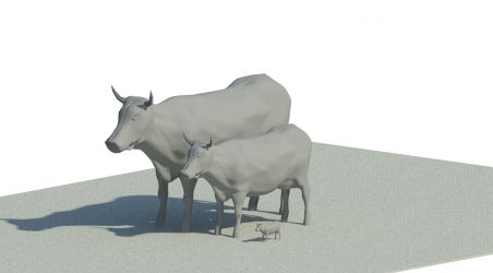
Some quotes from Making Breakthroughs in Revit: An Interview with Marcello Sgambelluri (the cow and elephant guy 🙂
“I realized … that Revit is much more than a program to be used to document buildings and I started my pursuit to push Revit to its limits so I could better myself.
Refocusing Phase: This is when I realize that there has to be a different way of doing something to achieve the end goal. I find a way.
there is nothing that motivates me more than when I hear the words “You cannot do that in Revit.”
My engineering training has helped me to step back and look at my Revit problems in a new light.
I am working on how to use the site modeling tools to model complex shapes… (*)
If you don’t know how to do something in Revit, try it. Remember it’s only a program—you can’t hurt it!
Get to know Revit and its environment. (**)
I realized that the only way I could achieve breakthroughs in Revit was to change my mindset about the program. “
Read more:
Making Breakthroughs in Revit: An Interview with Marcello Sgambelluri | AUGI
(*)
For my take on this, check out Using meshmixer to morph your Revit Topography
(**)
This goes hand-in-hand with the theme of this blog – finding out What Revit Wants. For further reading on this, check out The Revit Mind and What Revit Wants
 |
| Image from AUGI, by Marcello |
From Jeffrey McGrew on RevitForum (I’ve underlined key parts):
“While I respectfully disagree that rendering in Revit is a waste of time, for there are still times we do so, I totally agree with what you’re saying here. If you want to produce renderings from Revit models using anything but the built-in Mental Ray (and it’s vast limitations) then your best bet really is to link the Revit file into Max.
The new model linking in Max 2013 works very well, so we simply link our models, continue to do the ‘real work’ in Revit while we simply swap materials / plants / lights in Max and then use Octane Render to produce the images.
We’ve tried just exporting OBJs out of Revit or Max & bringing those into Octane Render, and the lack of control over UVs, instancing, entourage, etc. drove us back to using Max.
Just to be clear, I HATE Max. The UI drives me crazy, and it’s so crash-tastic that it’s a wonder we get work done sometimes. I’d much rather work with another program, but the Revit linking works so well, and the Octane Render plugin works so well, that well, I just suck it up. 😉
I’ve tried several rendering plugins for Revit, and run into the same problems. Even if there were a Octane Render plugin for Revit, I don’t know if we’d use it, unless it was as well integrated as the Mental Ray one is…
Jeffrey McGrew
Architect
”
Or is it a professional, individual endeavor? Or both? Five quick quotes from different parts of the latest JBIM:
When practiced correctly, BIM is meant to support collaboration across the facilities life cycle. BIM is the flow of information through a project, from inception to completion and throughout the entire life cycle of a structure.
Unfortunately, the industry is still developing separate models that are not communicating.
… as projects become bigger and more distributed, some teams struggle with the collaborative aspects inherent to BIM.
The utilization of BIM technology can result in improved occupational safety by connecting the safety issues more closely to construction planning.
IFC4 introduces the concept of material profiles, where axis-based components, such as beams, pipes and ducts, can be described by paths and cross-sections of materials, along with offsets relative to the axis and end points.
The journal seems to contain quite a bit of info on NBIMS, NBIMS-US and even IFC4.

Heads-up via:
Download BIM Can Be a Team Sport | Journal of Building Information Modeling – Fall 2012 | Bradley BIM
Ok, first of all, this is probably a bug. But in some ways, it is quite cool. Do this:
A few things:
Check out the video below – or jump straight to the cool part:
What it looks like:

I’ve been waiting for this! Keyboard shortcuts can make you ridiculously more productive in any CAD software, and that certainly includes Revit. Harry has made a little ‘tutor’ program that gives you visual cues on what Keyboard Shortcuts you can and should be using (like Veodin Keyrocket for Windows / Office).
Unfortunately, the full version isn’t free – but I guess the guy has to make a crust somehow 🙂 And I have a feeling that $5 will pay for itself in about half a day of improved productivity.
EDIT: Updated versions 27 Feb 2013
2012 Install 2013 Install Purchase License
Check it out:
“Free version provides reminders for shortcuts that contain the letter “W”. If you find it helpful and want reminders for all shortcuts, please purchase a license. “
Read more:
Download the Revit Keyboard Shortcut Tutor today! | Boost Your BIM – making Revit even better
The sheer volume of different BIM standards can be confusing in itself – and that is without even considering the
a) usefulness,
b) applicability,
c) practicality or
d) up-to-date-ness
of these different standards
In any case, a recent and decent list has been started at:
CAD addict: List of Existing BIM Standards
Some other useful links / lists:
Weblinks (big list of Standards on natspec.org)
BIM Standard and BIM Example Drawings Sharing (forum thread)
BIM Libraries | Whole Building Design Guide
BIM/IPD Aus (standards and guidelines with Australian focus)