When working with multiple linked files, you can utilize the ability of Revit to close Worksets in Linked Files, and in some cases this is a good visibility shortcut. Along these lines Simon over at BIM42 has written “a few line of code for set up every Scope Box, and Reference plane to the correct workset…”

See the code at:

Managing linked worksets | BIM 42

In a somewhat unexpected post, landarchBIM has described a method of inferring the movement of a Reference Plane that is driven by an angle parameter.  This probably falls outside of the “best practice” category, but it may be worth a read:
http://landarchbim.com/2014/04/01/rotating-reference-planes/

The key seems to be “that the plane must be constrained to the plane it wants to move along.”

Personally, I will probably stick to Reference Lines, because I don’t find them too difficult to understand or control.  But hey, whatever works for you!  Oh, and if you have any problems, contact landarchBIM 🙂

via
https://twitter.com/landarchBIM/status/451012524477927424

Reply:

Have you ever used the Workplane Viewer?  It looks like this:

When you open it, a new window opens and orients itself to the current workplane.  This window is the Workplane Viewer.

Revit Wants you to be understand workplanes, and to host things on correct workplanes in the model.  Virtually the entire model in Revit is built up on a series of 2D planes.  Additionally, being comfortable working in 3D views is an important Revit and BIM skill.  This is why you should use the Workplane Viewer…

A few impressive things about the Workplane Viewer:

  • Can be put on a secondary monitor and it remains open
  • It respects the Section Box of the currently active 3D view
  • Auto zooms to the extent of proper sketch elements when in a Sketch Mode
  • Keeps itself oriented to the current and correct workplane
  • It reports the currently set workplane in text form in the bar at the top of the window
  • Triggering Zoom Extents will affect both the current view and the Workplane Viewer
Interestingly, if a horizontal workplane is set (which is typically the case) and you are working in 3D, the Workplane Viewer will be giving you a Top View of the current 3D view – quite useful really.
The extent to which you can edit elements in the Workplane Viewer is dependant on the mode you are currently in.  Sketch modes allow you to edit sketch lines in the Viewer.  Editing a Family In-place allows you to select and modify extrusions.
It is a bit strange that the Workplane Viewer itself actually allows you to Orbit and use the Viewcube (meaning that you are no longer perpendicular to the current workplane.)  To fix this, go to a normal view and use the Set Workplane tool – the Workplane Viewer should now be back in sync with the current workplane.
In some respects, it is like the Replicate Window command, but the Workplane Viewer has a bit more intelligence when it comes to planes, and it is allowed to live on a secondary monitor.
Link to help:
Editing with the Workplane Viewer – WikiHelp

WhiteFeet Tools for Revit is a powerful set of add-ins that can make the impossible, possible.  I have posted about them before.  In this brief post, we look at how you can effectively Schedule the Reference Planes you have in a model.

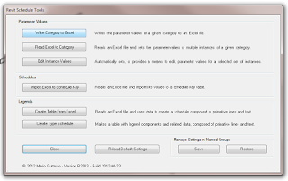
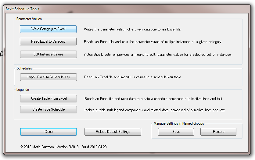
On the Add-ins Ribbon, choose Utility Tools – Schedule Tools:

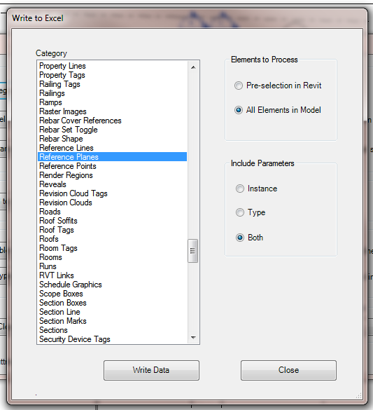
Pick Write Category to Excel, then select the Reference Plane category, All Elements in Model:

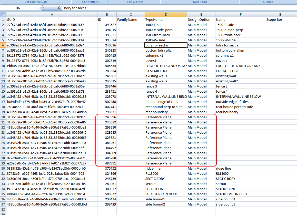
After you press Write Data, you will get something like this:

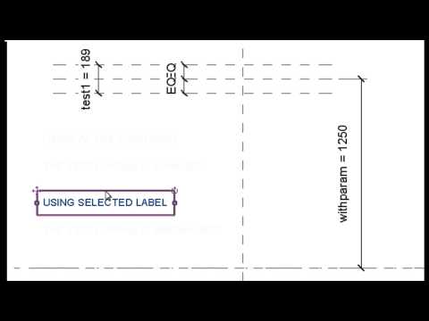
You can then sort the Data to find the unnamed versions, and then use the Element ID to select and name those Reference Planes, if you so desire.  In our office, an unnamed Reference Plane is fair game for deletion…

Also, some of you may have picked up that you can use this same process to export data from ANY CATEGORY in Revit – including those that you cannot schedule!

Find out how to obtain the Whitefeet software here:
Tools

There are at least two distinct ways to move an item via dimension edit in the Family Editor, but they can have very different results.  See video:

My video is directly derivative of one from Steve Stafford last week.  Steve demonstrated some interesting behaviour along basically the same lines at:
Revit OpEd: Two Minutes with Constraint Quirkiness

BIM Troublemaker proposes a solution that makes Reference Lines normal, at least in the short-term…and he adds a throwdown to Buildz at the end 🙂

I’ll start with my 3d triangle and draw a rectangle on its face. Lookie Dis! They are aligned in the direction i want!

I deleted 2 lines i didn’t need, slapped reference points hosting my extrusion profile on the 2 remaining, and then pulled them to the edges of my triangle…

Read more / via
BIM Troublemaker: Aligning Reference Lines

Hey Revit, look what I can do!

if you bring a #Revit model into #Vasari the grid lines show up in 3D like reference planes-that can be really useful for coordination

via @pete1352 Matt Petermann on
Twitter / @pete1352: if you bring a #Revit mode …

This is actually pretty cool.

The same goes for Levels – in Vasari they show up in the 3D View.  Obviously, normal Reference Planes also show up in 3D:

I recently viewed the class All In the Family: Creating Parametric Components In
Autodesk® Revit® (Matt Dillon) AB4013
, on AU Virtual.

It was a class targeted at users with Intermediate expertise.

I learned this:
The Left hand side of a Reference Plane is the ‘positive’ + side.  The ‘handedness’ of the plane is derived from start and end points of plane (the start point of the reference plane is the first point you click when drawing a new reference plane).

When you set a particular workplane as active, and use the default positive extrusion depth, the extrusion will be created on the positive side of the plane.

I have attempted to display this effect in the image below:


I’m sure this has been described elsewhere, but it was a eye-opener for me!

No, not aeroplanes: we are talking about Reference Planes. So, the tip is:

Always name reference planes that you intend to keep and use.

Reference Planes lie at the very core of What Revit Wants. Revit is a program, so it needs parameters. In order for understand objects in 3D space, it needs to establish a ‘plane’ to work from. Obviously, Reference Planes are the basic, garden variety type of Revit plane – there are also Grids and Levels. These are just planes that do some special things, like host a view.

If you want to quickly see what planes exist in your project, open a 3D view and then start the ‘Set Work Plane’ command. This dialog shows all the NAMED planes, including grids and levels. Can you start to see why you should name Reference Planes you intend to keep and use? That way, you can quickly make them ‘current’ by using this command.

This also allows you to clean up your drawing. If you adopt this tip, let’s say you come back to a drawing a few months later and it is absolutely cluttered with Reference Planes. Which ones can you safely delete? Well, you have named all the important ones, so you can delete the rest!