Steve Stafford and Aaron Maller are both awesome Revit guys.  Both of them have a Screencast library of videos that you can freely view.  Here are the links:

RevitOpEd’s library

aaronmaller’s library

You can also subscribe to an RSS feed of Steve’s Screencast videos.

Do you have a set of Revit-related videos in a library that you would like to share with us?  Please leave a comment with a link…


Geometry Gym has released an IFC importer for Vasari Beta – links below:

ggRevitIFC2013x64 v0.0.37.msi (13th September 2012) REVIT 2013

ggRevitIFC2012x64 v0.0.37.msi (13th September 2012) REVIT 2012

ggVasariIFC v0.1.0.msi (18th September 2012) VASARI

64 Bit Vasari, Revit 2012 and Revit 2013 Addon to import IFC files.
Addon undergoing rapid development. Please use with care and send suggestions and observations.

via
Downloads – Geometry Gym

Image from Geometry Gym

Heads-up:
Geometry Gym: IFC Importer for VASARI

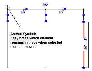
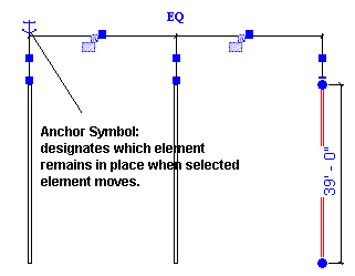
In a multi-segmented, equality constrained dimension, you can use the anchor symbol to designate the anchored element. The element that is anchored remains stationary while you move other elements in a dimension.  

  • Click and hold the anchor symbol. A witness line appears for the anchor.
  • Drag the anchor symbol to the element you want to anchor.
  • Move any of the unanchored elements referenced in the dimension.
  • The element accompanied by the anchor does not move.

From:
Anchoring Elements Referenced in Multi-Segmented Dimensions – WikiHelp

Also refer to my previous post:
What does the Revit equality dimension anchor do?

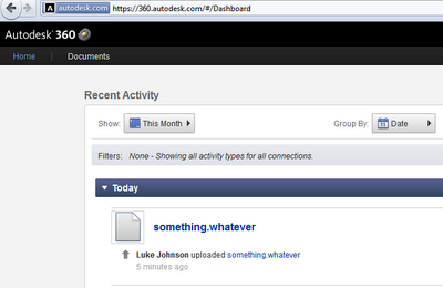
Did you know that you have an offline copy of your Autodesk 360 Cloud data?  It lives here:
C:UsersUSERNAMEAppDataLocalAutodeskAutodesk SyncCloudCLOUDUSERNAME

If you put a file in this folder, it will automatically get Synced to your online 360 account.  It doesn’t seem to matter what the filetype is – it uploaded my something.whatever file quite happily.

I assume there is a system setting somewhere that sets the sync interval.

In any case, you could make a shortcut to this folder on your Desktop and use it as online file storage, if you so desire…

via
Google Translate
of
http://bimblog.typepad.com/autodesk_bim_blog/2012/09/wenn-sie-dateien-%C3%BCber-bim-360-produktschnittstellen-wie-sie-zb-in-autocad-architecture-enthalten-sind-von-ihrem-lokalen.html

You have a Revit file with some custom hatch patterns (filled regions / fill patterns) in it.  You want to turn them into PAT files for re-use in AutoCAD or some other drafting program.  Here’s how:

  1. Make a Drafting View in Revit with a couple of Filled Regions in it.  
  2. Set the filled Regions to the Revit Hatch Patterns that you want to export to PAT files.
  3. Export the Drafting View to a 2000 version DWG file
  4. Open the DWG file in AutoCAD
  5. In AutoCAD, APPLOAD then browse to getpat.lsp file.  To get this file, right-click and Save Target as from this link.
  6. After loading the lisp file, File – Save As the DWG, to something in the same directory (this step just makes AutoCAD and the LISP aware of where the PAT files should be saved)
  7. Then, type GETPAT
  8. Select the hatch you want to export.  It *should* be saved as a PAT file to the same directory that the DWG file is in.

EDIT – you could also try this method:
What Revit Wants: Native Revit can make PAT files too – you just have find them …

In response to this tweet:

Related forum post:
http://forums.augi.com/showthread.php?71833-Creating-a-pat

More free lisps:
http://www.turvill.com/t2/free_stuff/index.htm

Links via https://twitter.com/paulfaubin

I just grabbed them and added them to a playlist for easy access… about 3.5 hours worth!

Here are the basic video titles in the playlist (as at 17 September 2012):

Revit Architecture: How to make global changes

Understanding the building information modeling process

Revit Architecture: The Ribbon and Quick Access Toolbar

Revit Architecture: How to use the modification tools

Revit Architecture: How to work with DWG files

Revit Architecture: How to add curtain walls

Revit Architecture: How to create key styles

Revit Architecture: How to use the Blend tool

Revit Architecture: Working with the Project settings

Understanding Revit Architecture’s Family Editor

How families work in Revit Architecture

How to work with Revit’s Family Editor

How to work with Revit’s reference planes

How to use Revit Architecture’s camera settings

How to use the Sun Path feature

How to use non-photorealistic renderings

What you should know about Revit Architecture

Rivet Architecture design asset management + general overview

Rivet Architecture tutorial: Building an in-place mass

Revit Architecture tutorial: Working with curtain panels

Revit Architecture: Exploring advanced stitching strategies

Revit Architecture tutorial: Understanding adaptive points

Revit Architecture tutorial: Working with DWG files

Revit Architecture: Creating custom walls

Revit Architecture: How to work with floors

Listening dimensions is the technical term for the little blue dimensions that appear as you start drawing a line in Revit.  The bold entry is the one that Revit is ‘listening’ to the keyboard for.  When it comes to angular dimensions, if you start drawing a line then hit TAB it basically ignores the Angular snap increments and shows you the exact angle at your cursor position (go Manage – Snaps to see the increments).  Also, if you put an increment in the Angular dimension snap increments that is not divisible into 360, Revit will basically ignore it.

Holding Shift will constrain you to either vertical or horizontal directions.

In AutoCAD, you can access either the angle or the length of a line when creating a new line.  Sadly, Revit does not allow you to access the angle while creating a new line or wall – you can only enter a Length (as this is the bold listening dimension at creation time).

Basically, then, we need to consider some workflows for allowing angular entry.  Most of these are time consuming (see below).

Workflows:
Option 1 –

  1. Have a Drafting View open, with a line in it
  2. Select the line
  3. Adjust the angle
  4. Copy / paste into your current working view

Option 2 –

  1. Select a Plan View crop region
  2. Rotate it to the specific angle that you want to work with
  3. Start drawing a line
  4. Use SHIFT to contrain the movement (Revit respects the view crop boundary as defining the vertical and horizontal directions)

Option 3 –

  1. Draw line
  2. Select line
  3. Use angle dimension box

Option 4 –

  1. Draw line
  2. Select line
  3. Trigger rotate command

Do you have a better solution for angular entry at element creation time?  It wouldn’t be hard to come up with a better way than those described above.

Here is some more information I found while exploring this issue …

Unit entry:
=45d1 results in 450mm?  Why?
Also refer to Entering different units while using Revit natively

Great thread:
the value typed goes into the “listening” temporary dimension (which is the one that is bold).
http://forums.augi.com/archive/index.php/t-40708.html  (note – this thread is AWESOME for shortcuts and tricks)

Wikihelp:
If there is no linear dimension, you can enter an angular dimension, if applicable.
http://wikihelp.autodesk.com/Revit/enu/2013/Help/00001-Revit_He0/1468-Document1468/1744-Annotati1744/1745-Dimensio1745/1786-Listenin1786#GUID-84FFE118-6EF7-4747-8DF7-AE675818645E

Failed forum posts asking for listening angular dimensions:
http://forums.autodesk.com/t5/Autodesk-Revit-Architecture/Listening-Dimensions-Line-angle/td-p/2487339
http://forums.augi.com/showthread.php?134150-Listening-Angular-Dimension
http://forums.augi.com/showthread.php?46169-listening-dimensions-for-angles

Line drawing tip – Radius between straight lines:
select Radius and specify a value.
A radius creates fillets at the specified radius between line segments, allowing you to create a rounded chain of lines. A line must be joined to the end of another line for a fillet to display. If a line is connected to more than one line, a fillet cannot be created.
The following image shows line segments sketched without Radius selected and line segments sketched with Radius selected.

via
Sketching a Line – WikiHelp

Steve’s post recently reminded me of something I have done in the past – using multiple pseudo usernames to access the same Central File in different instances of Revit.

Let’s say that you wanted to render a certain scene in Revit, and then save the resultant image to the Project (a Central File).  As this render could take 10 minutes, you want to keep working on something useful in the same Central File.  What to do?

You just need to open a new instance of Revit and change the Username, then open a Local Copy of the Central as per usual.  You now have 2 instances of the same Central model open, and you can work in and Synchronize from both of them … obviously you are going to need some decent hardware if you are working on a large central file with links.  Set the first instance to render, and work in the second instance while that is happening (keep in mind that local renders in Revit can use multiple cores, so you may want to think about manually adjusting core affinity).

The username can be changed in the Revit Options dialog:

From Steve’s post:
You can however change your username anytime you want when you work in a central file. It isn’t a great idea to actually work this way, switching usernames as you go. It is however a way to clear out users that have not relinquished worksets properly though. When nobody else is working on the project you can open a central file and pretend to be the ill mannered users that haven’t relinquished elements properly. It’s another reason you might consider working in a central file, even though it is generally frowned upon.

Read more at:
Revit OpEd: Changing a Username

Here are a couple of system utilities that may help you to squeeze maximum performance out of your hardware (to speed up Revit, of course).  Actually, my FX580 was struggling a bit with Showcase, so I wanted to overclock it a bit to make the augmented reality plugin work a bit more smoothly…

GPU-Z is a handy information tool for your video card.  If you are overclocking, it will tell you the current clock speed, as well as the default.  It will also tell you the driver and Forceware version that you are running, as well as additional advanced performance information.

Download TechPowerUp GPU-Z v0.6.4 | techPowerUp

(also, if you are overclocking a GPU, check out hwbot – it will give you an idea of the average overclock you can achieve using air cooling only for a given GPU model)

Core Temp will give you advanced processor information, including temperature and load for each core on your CPU.

Dev Eject will help you remove USB devices safely, even if Windows is struggling to do so.