Let’s say you have some linked RVT files and you are using ‘By Linked View’ for visibility. What if you just want to hide off a single type of Filled Region from that Linked View? Is it possible? Yep, here’s how:

  1. Make a new View Filter for Detail Items that looks like the below, using Family Name equals Filled Region, and the relevant Type as properties:
  2. Add this View Filter to your View or View Template
  3. In the visibility properties for that Link, make sure you set Filters to By Host View…

Done!

    You can use HATCHGENERATEBOUNDARY in AutoCAD to recreate the boundary of a Filled Region that you exported to DWG.

    You may be asking “why!” Well, if you have a bunch of Filled Regions and their sketch lines are all set to Invisible Lines, this may be one of the quickest ways to get a visible, printable outline of those filled regions in Revit

    Here’s a quick video:

    https://screencast.autodesk.com/main/details/6760f260-29f9-4690-890b-2516ac507f24

    If you have problems with your Revit Filled Region hatch patterns displaying grayscale when they should be black, its probably because Revit thinks that the lines are too close together for the scale of view that you are using.

    What Revit wants is for you to increase the scale or spacing between the individual lines of the Filled Region pattern – then it will switch back to black, as it should be.

    Using a Model pattern, I was able to observe the pattern go from light gray to black as I changed the scale (spacing) between the lines.

    Interestingly, using a Drafting pattern allowed me to put the lines in the Filled Region much closer together…

    Some more info at:
    RevitCity.com | filled region pattern color changes when drawing scale changes

    You have a Revit file with some custom hatch patterns (filled regions / fill patterns) in it.  You want to turn them into PAT files for re-use in AutoCAD or some other drafting program.  Here’s how:

    1. Make a Drafting View in Revit with a couple of Filled Regions in it.  
    2. Set the filled Regions to the Revit Hatch Patterns that you want to export to PAT files.
    3. Export the Drafting View to a 2000 version DWG file
    4. Open the DWG file in AutoCAD
    5. In AutoCAD, APPLOAD then browse to getpat.lsp file.  To get this file, right-click and Save Target as from this link.
    6. After loading the lisp file, File – Save As the DWG, to something in the same directory (this step just makes AutoCAD and the LISP aware of where the PAT files should be saved)
    7. Then, type GETPAT
    8. Select the hatch you want to export.  It *should* be saved as a PAT file to the same directory that the DWG file is in.

    EDIT – you could also try this method:
    What Revit Wants: Native Revit can make PAT files too – you just have find them …

    In response to this tweet:

    Related forum post:
    http://forums.augi.com/showthread.php?71833-Creating-a-pat

    More free lisps:
    http://www.turvill.com/t2/free_stuff/index.htm

    Do you love or hate Revit Fill Patterns?  Here is a collection of some tips and tricks related to Fill Patterns, or ‘hatching’ in AutocadSpeak.

    Overview
    On your system, open up your Revit installation directory, and the Data subdirectory.  There should be two PAT files here:
    revit.pat (This file contains the standard set of custom fill patterns distributed with Autodesk Revit.)
    revit metric.pat

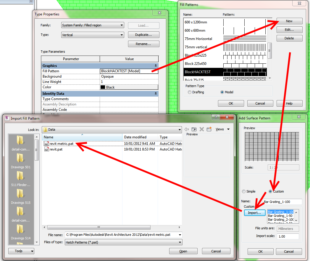
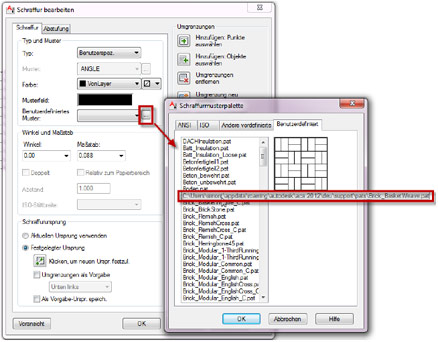
    If you want to load some of these patterns into your project, use the normal procedure (Fill Patterns – New – Custom -Import).  Copy the location of the PAT files from your navigation bar in Windows 7 into the dialog and hit Enter.  Click on one of the files and you can select one of the patterns to load.

    General Hatch tips
    (refer to “C:Program FilesAutodeskRevit Architecture 2012Datarevit.pat”)

    • Once a pattern is imported, it is stored in the project, independent of the original file.
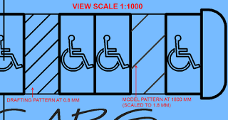
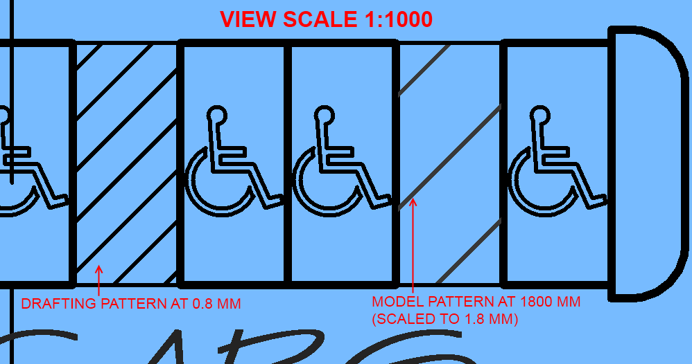
    • Drafting patterns are defined in paper units. If you import the pattern at scale 1 and print at 100% zoom, the pattern’s dimensions on paper will be exactly as specified in the file, regardless of view scale.

    Location of Default Revit fill patterns
    Default Revit fill patterns are stored in the revit.pat and revit metric.pat files in the Revit program group Data directory. The revit metric.pat file contains various metric masonry and iso patterns. 
    via Creating a Custom Fill Pattern – WikiHelp

    Differences between AutoCAD and Revit .PAT files
    (refer to “C:Program FilesAutodeskRevit Architecture 2012Datarevit.pat”)

    • AutoCAD has an 80-character line size limit, Revit’s is 4096.
    • AutoCAD allows arbitrary sequences of dashes, spaces and dots, Revit coerces them into dash-space format by inserting zero spaces and dashes.
    • AutoCAD has a notion of dots, Revit expands them (including the zero dashes it inserted) into short dashes.
    • AutoCAD has a maximum of 6 components to a line pattern, Revit has no limit.
    • AutoCAD does not allow spaces in a pattern name, Revit does.
    • AutoCAD allows only one pattern per a custom file, with pattern name matching file name, and with the file residing in a known location. Revit has none of these restrictions.
    • AutoCAD and Revit utilize different logic to decide whether a pattern is acceptable.

    I previously reposted a method on how to bring AutoCAD hatches into Revit with correct scaling.

    The German Autodesk AEC team have put together a step by step tutorial on exporting a PAT file from AutoCAD and then importing it into Revit.

    They have even shown how to correctly scale the imported PAT files numerically – rather than the haveAguessAndSee method that I generally use.

    Image from autodesk.de

    Here is a link to a translated version of the post:
    Google Translate

    Here is the original post:
    http://www.autodesk.de/adsk/servlet/pc/item?siteID=403786&id=17857940

    Who can put it better than Google Translate?

    Much fun and success with Revit Architecture
    , Autodesk AEC team

    The Revit Clinic has posted a nice little display order workaround for Filled Regions in Title Blocks.  I have a feeling that this workaround may also be useful in other situations…

    1. Start a new Revit generic annotation family.
    2. Cut & paste the filled region[s] into the generic annotation family.
    3. Load the generic annotation family into the title block family.

    While the display order may appear incorrect in the title block family, it should now appear print in the expected order once loaded back into the project.
    via
    Filled Region Blocking your Lines in a Project Title Block? – The Revit Clinic