Massive free time saver for changing or swapping fonts in a Revit project!

Unfortunately, its not quite ‘everywhere’ – Generic Annotations need to be manually fixed. You can copy a text type to a Generic Annotation by first placing an instance of that text type on a Sheet in the Project.

Download at:
Sofistik Bimtools 2015
Sofistik Bimtools 2016
Sofistik Bimtools 2017

But what about SecretInternal Types?
This tool created another annoying problem for me… it exposed a whole bunch of  ‘secret internal types’ in Revit.

How do we solve the SecretInternalTypes?

Here is what it they look like, along with how to fix them by deleting selectively with Dynamo.

Arrowheads:

Fixing / removing SecretInternal arrowheads with Dynamo:

Dimensions:

Fixing / removing SecretInternal Dimensions with Dynamo:

Removing the arrowheads resulted in a broken Elevation mark:

To fix this, I deleted the broken types and families (the Elevation Circle and Pointer) using the Project Browser, and then Transfer Project Standards – Elevation Types from a known good project.

So, now my fonts are changed and my SecretInternalTypes are fixed 🙂

When working in 3D in Revit, you *can* use the normal dimension tool *if* you first set the Workplane. However, this can get annoying. Why not make a 2 point adaptive family, with a reporting parameter, so that you can just place the family (two clicks) and then check the instance parameter as shown below?

Update: V2 with arrowhead and tag in project Download here

Adaptive dimension family (2016), Download here


Revit wants you to make your own better, faster way sometimes…

This little family is surprisingly useful:

Particularly good for situations where you want to dimension something but you can’t access the “host elements” – or you are worried the host witness lines may get changed or deleted (which would also delete the dimension.)

You could customize it to suit your own graphic requirements eg. add some dimension arrows and witness lines to it.

Download:
https://drive.google.com/file/d/0B1dGdRkpk2beWDZxZWdsa0ZoNlU/edit?usp=sharing

EDIT  Due to a number of requests, here is a 2012 version for 2012 and 2013:
https://drive.google.com/file/d/0B1dGdRkpk2bebHV5XzdSSWVzZWM/edit?usp=sharing

Revit deals in realities.  The reality is, many Rooms are not rectangular.  So we can forgive vanilla Revit for not having a built in tool or method that could only really ‘guess’ at X and Y room dimensions for irregularly shaped rooms.

There are two workarounds that I think can be useful:

  1. A Room Schedule that calculates X and Y dimensions for rectangular rooms only
  2. A Model Family with built in nested annotation labels that needs to be manually stretched and updated to the assumed X / Y dimensions of the Room.  Just place the family and then adjust the grips.

I can’t take credit for the Calculation method.  This uses a formula based on Perimeter and Area to establish calculated values for X and Y room dimensions in a Schedule.  I downloaded an RVT back in 2008 that demonstrated this method — from … somewhere.

Similarly, I can’t really take credit for the Model Family with Annotation Labels idea for the family either.  Daryl Gregoire posted it years ago in a series of videos, and it was mentioned in this post as well.

Download this file to see both methods in action.  Be sure to review both the Floor Plan and the Schedules to see how it all works together.

I chose Casework because it has built in X, Y and Z parameters – meaning I did not have to use Shared Parameters.  I control visibility by placing these Casework families on a secondary Design Option.  You could actually use a standard Casework Tag instead of the built in annotation if you prefer.  The Casework Schedule is filtered by Type Comments, and the other good thing about Casework is that we can Schedule the Room that the Model family lives in.

Feel free to comment, even if you think both methods are a bad BIM idea 😉

There are at least two distinct ways to move an item via dimension edit in the Family Editor, but they can have very different results.  See video:

My video is directly derivative of one from Steve Stafford last week.  Steve demonstrated some interesting behaviour along basically the same lines at:
Revit OpEd: Two Minutes with Constraint Quirkiness

In a multi-segmented, equality constrained dimension, you can use the anchor symbol to designate the anchored element. The element that is anchored remains stationary while you move other elements in a dimension.  

  • Click and hold the anchor symbol. A witness line appears for the anchor.
  • Drag the anchor symbol to the element you want to anchor.
  • Move any of the unanchored elements referenced in the dimension.
  • The element accompanied by the anchor does not move.

From:
Anchoring Elements Referenced in Multi-Segmented Dimensions – WikiHelp

Also refer to my previous post:
What does the Revit equality dimension anchor do?

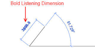
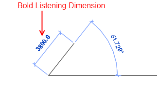
Listening dimensions is the technical term for the little blue dimensions that appear as you start drawing a line in Revit.  The bold entry is the one that Revit is ‘listening’ to the keyboard for.  When it comes to angular dimensions, if you start drawing a line then hit TAB it basically ignores the Angular snap increments and shows you the exact angle at your cursor position (go Manage – Snaps to see the increments).  Also, if you put an increment in the Angular dimension snap increments that is not divisible into 360, Revit will basically ignore it.

Holding Shift will constrain you to either vertical or horizontal directions.

In AutoCAD, you can access either the angle or the length of a line when creating a new line.  Sadly, Revit does not allow you to access the angle while creating a new line or wall – you can only enter a Length (as this is the bold listening dimension at creation time).

Basically, then, we need to consider some workflows for allowing angular entry.  Most of these are time consuming (see below).

Workflows:
Option 1 –

  1. Have a Drafting View open, with a line in it
  2. Select the line
  3. Adjust the angle
  4. Copy / paste into your current working view

Option 2 –

  1. Select a Plan View crop region
  2. Rotate it to the specific angle that you want to work with
  3. Start drawing a line
  4. Use SHIFT to contrain the movement (Revit respects the view crop boundary as defining the vertical and horizontal directions)

Option 3 –

  1. Draw line
  2. Select line
  3. Use angle dimension box

Option 4 –

  1. Draw line
  2. Select line
  3. Trigger rotate command

Do you have a better solution for angular entry at element creation time?  It wouldn’t be hard to come up with a better way than those described above.

Here is some more information I found while exploring this issue …
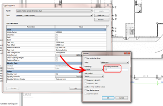
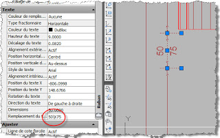
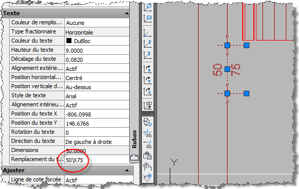
Unit entry:
=45d1 results in 450mm?  Why?
Also refer to Entering different units while using Revit natively

Great thread:
the value typed goes into the “listening” temporary dimension (which is the one that is bold).
http://forums.augi.com/archive/index.php/t-40708.html  (note – this thread is AWESOME for shortcuts and tricks)

Wikihelp:
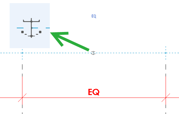
If there is no linear dimension, you can enter an angular dimension, if applicable.
http://wikihelp.autodesk.com/Revit/enu/2013/Help/00001-Revit_He0/1468-Document1468/1744-Annotati1744/1745-Dimensio1745/1786-Listenin1786#GUID-84FFE118-6EF7-4747-8DF7-AE675818645E

Failed forum posts asking for listening angular dimensions:
http://forums.autodesk.com/t5/Autodesk-Revit-Architecture/Listening-Dimensions-Line-angle/td-p/2487339
http://forums.augi.com/showthread.php?134150-Listening-Angular-Dimension
http://forums.augi.com/showthread.php?46169-listening-dimensions-for-angles

Line drawing tip – Radius between straight lines:
select Radius and specify a value.
A radius creates fillets at the specified radius between line segments, allowing you to create a rounded chain of lines. A line must be joined to the end of another line for a fillet to display. If a line is connected to more than one line, a fillet cannot be created.
The following image shows line segments sketched without Radius selected and line segments sketched with Radius selected.

via
Sketching a Line – WikiHelp

Revit au Quotidien has picked up a few mildly scary issues when exporting to DWG from Revit 2013, one seems to be related to dimensions with Text Below, the other to EQ display of actual dimensions.

Have you been experiencing any of these issues?

Read more at:
Text below
Google Translate of http://revitauquotidien.blogspot.com.au/2012/05/revit-2013-bug-l-vers-autocad-dwg.html

EQ display
and Google Translate of http://revitauquotidien.blogspot.com.au/2012/05/revit-2013-bug-l-vers-autocad-dwg-n2.html