In ye olde AutoCAD days, there were a plethora of ways to mess with your fellow users. The sheer amount of obscure yet powerful system variables gave endless opportunities for frivolity.
In Revit, not so much. The system works. It seems Revit does not want you to prank your coworkers, right? Here is a little story …
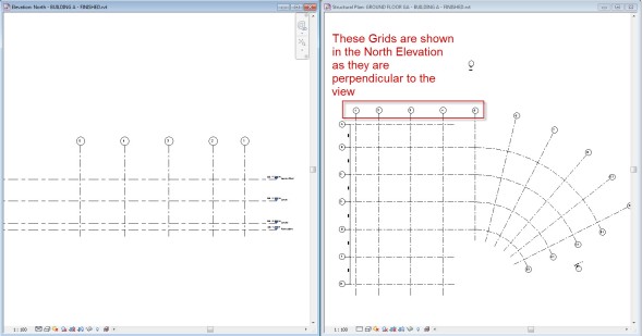
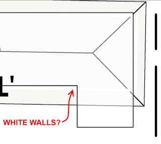
We were having trouble finding a particular Revit link, or more specifically, the walls in a particular Revit link. So we drew a roof, and the view looked like this:
Ok, so the answer seems easy. Walls are overriden, right? Let’s have a look in the View Template:
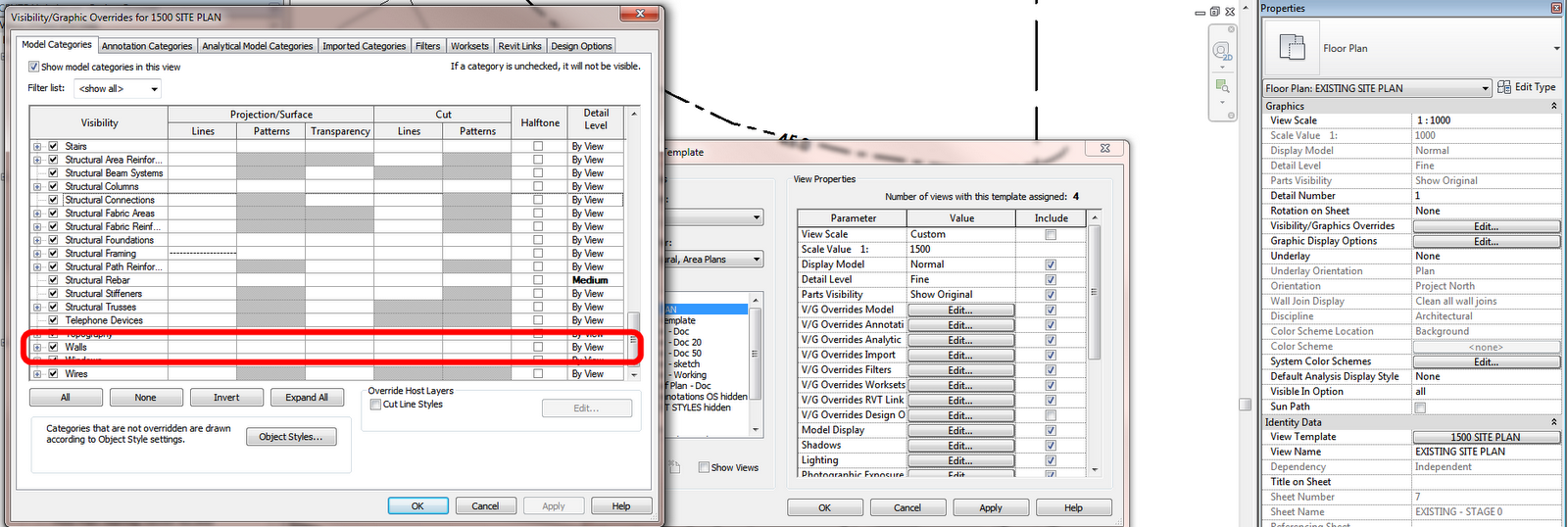
According to the Visibility / Graphics of Model in the View Template, everything seems cool. Walls aren’t overridden. All of the cells look the same, in their default state.
Or are they?
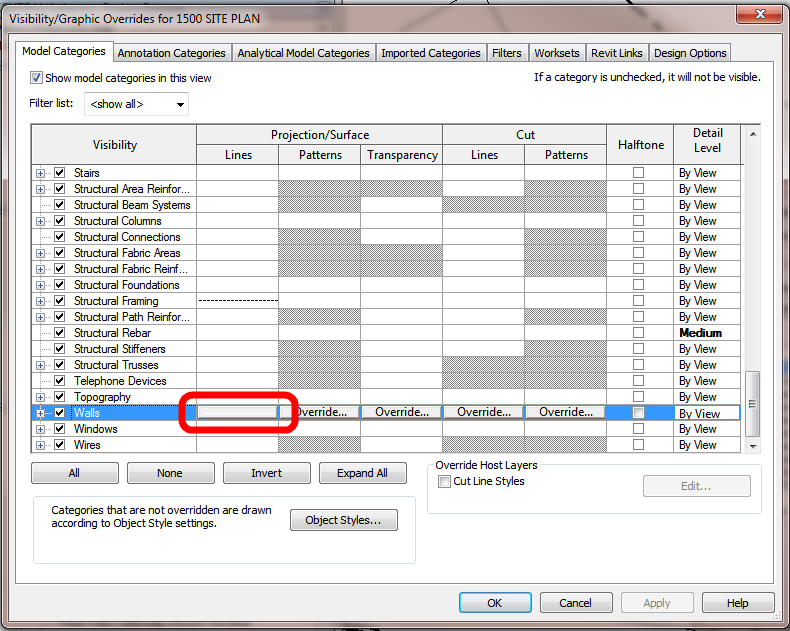
Let’s select the Walls row:
A tiny, almost invisible sliver of white appears under the Project Lines column, while all of the other columns show Override (indicating they are not overridden).
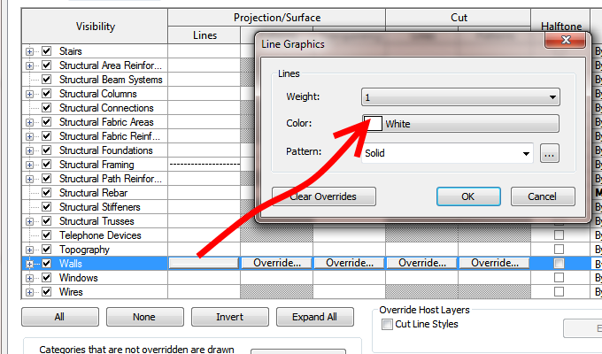
So what exactly is happening? Let’s click on the Projection Lines override for Walls:
We get very little feedback from Revit as to what is happening until we select the actual row. Why? Because the override is set to white!
This is certainly a trap for new, or old, Revit players. If you read this blog, you are prepared.
If you don’t, you may be pranked by some White Line overrides in the very near future 🙂 Let the shenanigans begin…


 6:12 Vasari Talk 18: Grasshopper to Vasari- Introductions
 5:23 Vasari Talk 18: Grasshopper to Vasari – Jon Mirtschin on Geometry Gym
 9:41 Vasari Talk 18: Grasshopper to Vasari – Hiroshi Jacobs on Chameleon
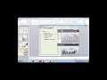 10:23 Vasari Talk 18: Grasshopper to Vasari — Tim Meador on Hummingbird.mp4
 12:00 Vasari Talk 18:Grasshopper to Vasari — Nathan Miller on OpenNURBS
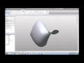 18:25 Vasari Talk 18: Grasshopper to Vasari — Discussion.mp4