
In Revit 2013, with Component Railings, you can unpin certain elements and modify them. For example, you can unpin a selected component Railing (Top Rail Type or Hand Rail Type) and swap it out for a different type. Similarly, you can unpin and swap out posts. However, you can also MOVE component posts after you unpin them. Some of this functionality is beginning to resemble Curtain Walls…
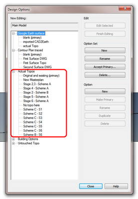
A word on terminology: pre-2013 we had Balusters. These appeared as a top level element under the Railings category in the Project Browser. In Edit Family mode, the Family Category and Parameters dialog did not tell you ‘this is a Baluster’. You could look in the Properties Palette and it would say Family: Balusters. In Revit 2013, the above condition still exists for Balusters (backward compatibility). However, the new component Posts are termed “Supports” and Supports is a proper sub-category of Railings (properties in Family Editor shows Family: Supports). Confused yet? If you want to dig a little deeper, check out the diagram on this page.
Ok, back to unpinning the posts (supports)–
What you need:
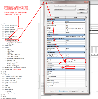
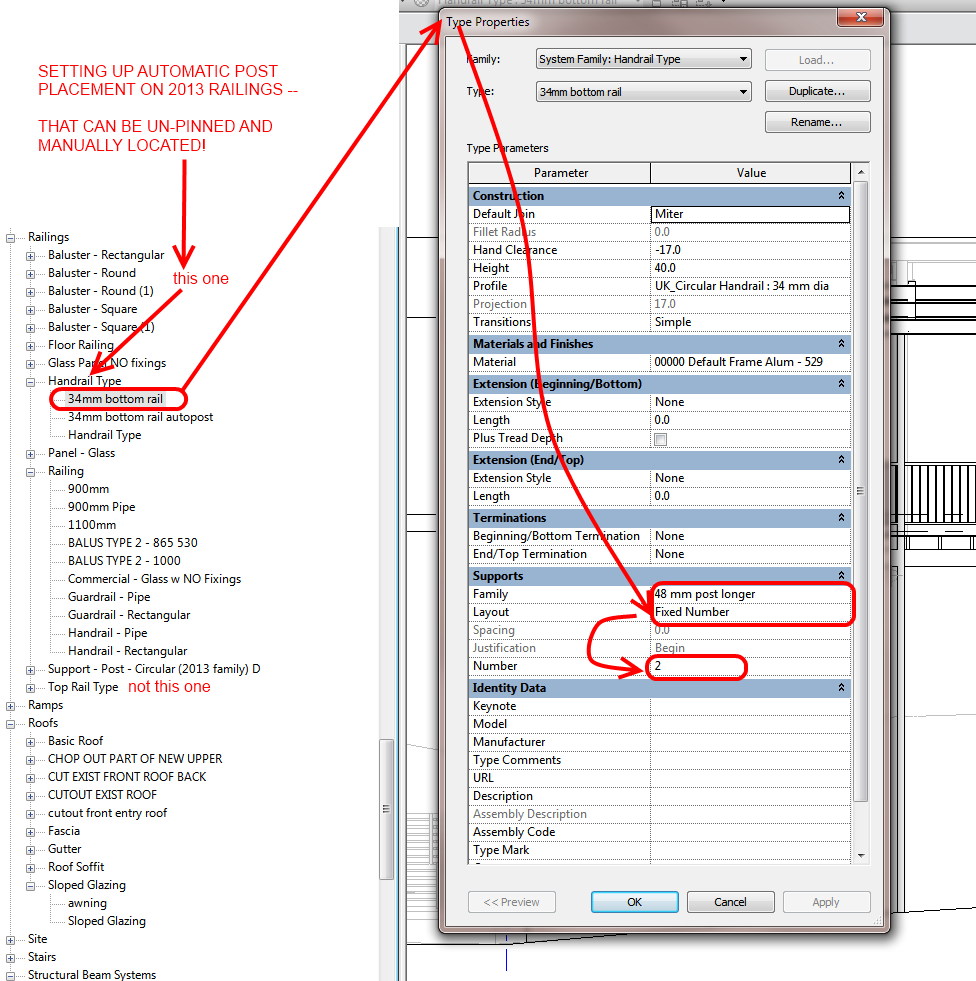
- A 2013 Handrail Type with Supports set to Fixed Number
- A Supports family applied to the above type
What you do:
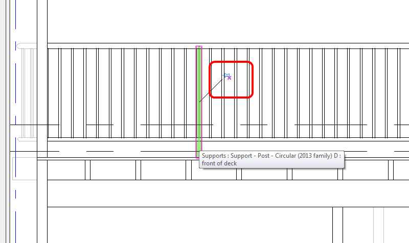
- Draw the railing
- The fixed number of posts will be auto spaced along each segment of Railing
- Select each post, unpin it and then either Drag (with mouse) or Nudge (with arrow keys) into position.
I have created a Supports family which allows resizing at both top and bottom – so I can create new types for various situations, unpin and then swap.
For a crash course in Revit 2013 component railings, check out:
Revit 2013 railings – almost 7 months old, but have you used them?


