The release of the Advanced Spaceborne Thermal Emission and Reflection Radiometer (ASTER) Global Digital Elevation Model Version 2 (GDEM V2) was announced on October 17, 2011. This data can be downloaded and imported to Infraworks.

Here’s how:
1) Go here:
http://gdex.cr.usgs.gov/gdex/

2) Create an account / login

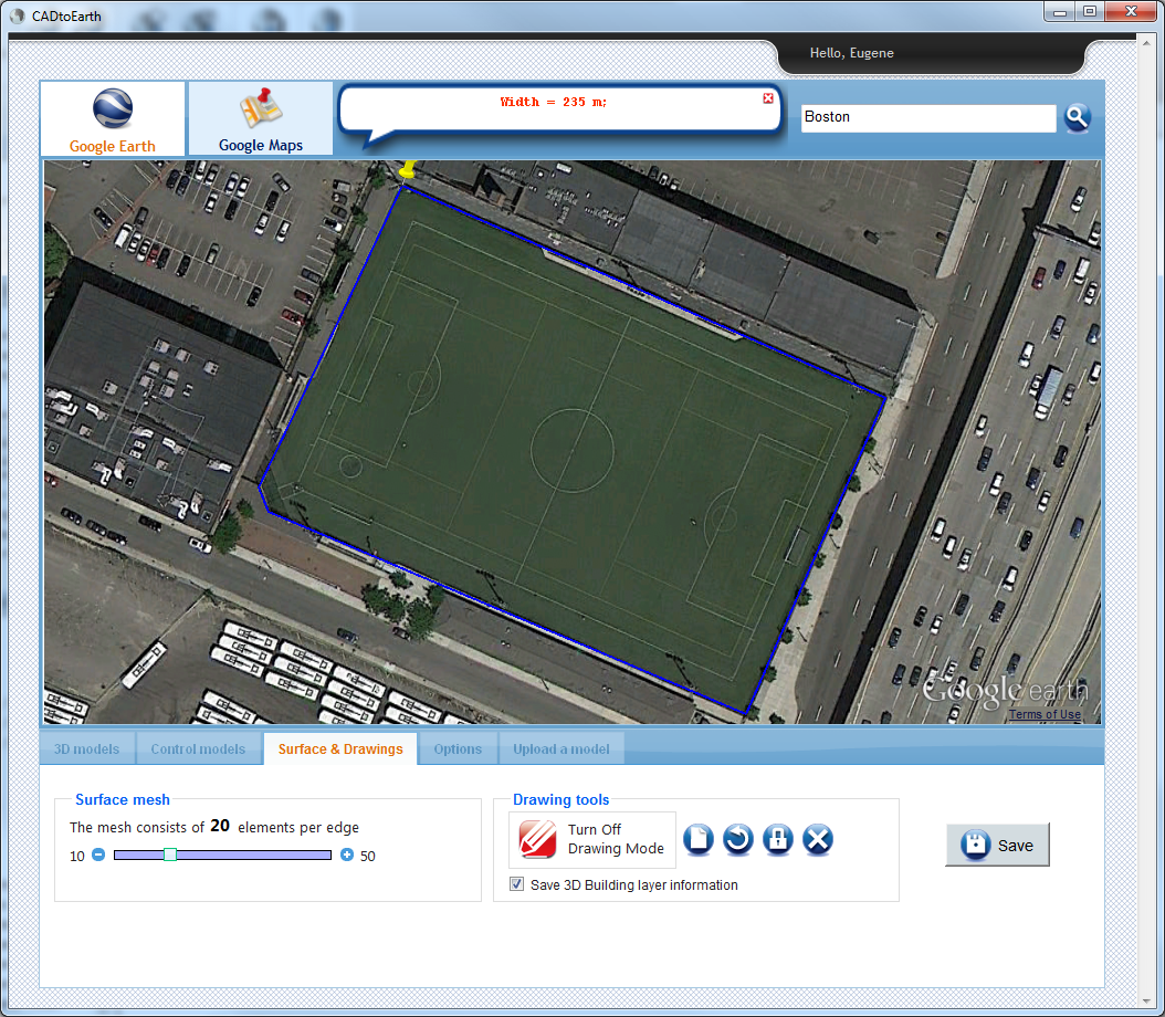
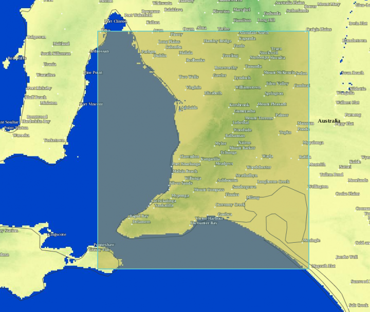
3) Browse the world, then Select a region using one of the tools, such as Rectangle

4) Download using ArcASCII

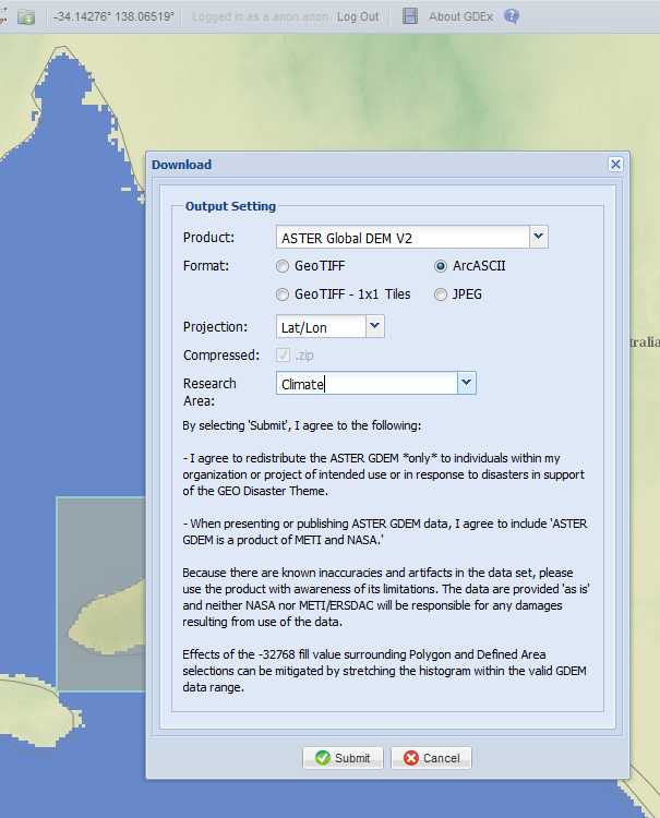
5) Back in Infraworks: Import from file, Raster

6) Select the ArcASCII file

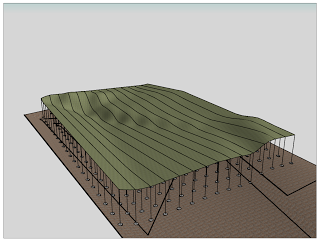
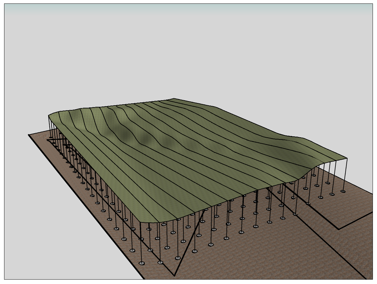
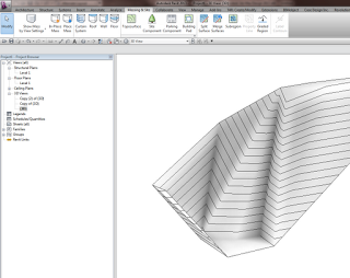
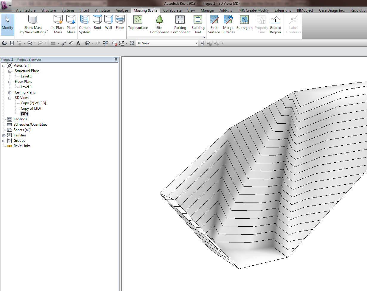
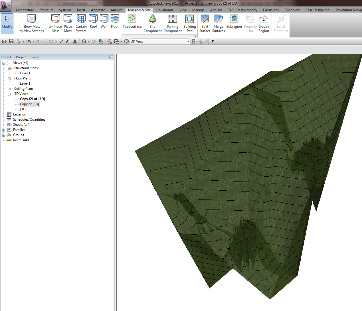
7) Right click the source in Infraworks and pick Refresh. Your topo should now be visible:

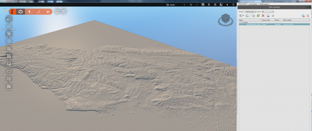
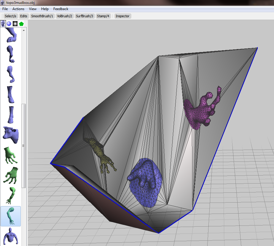
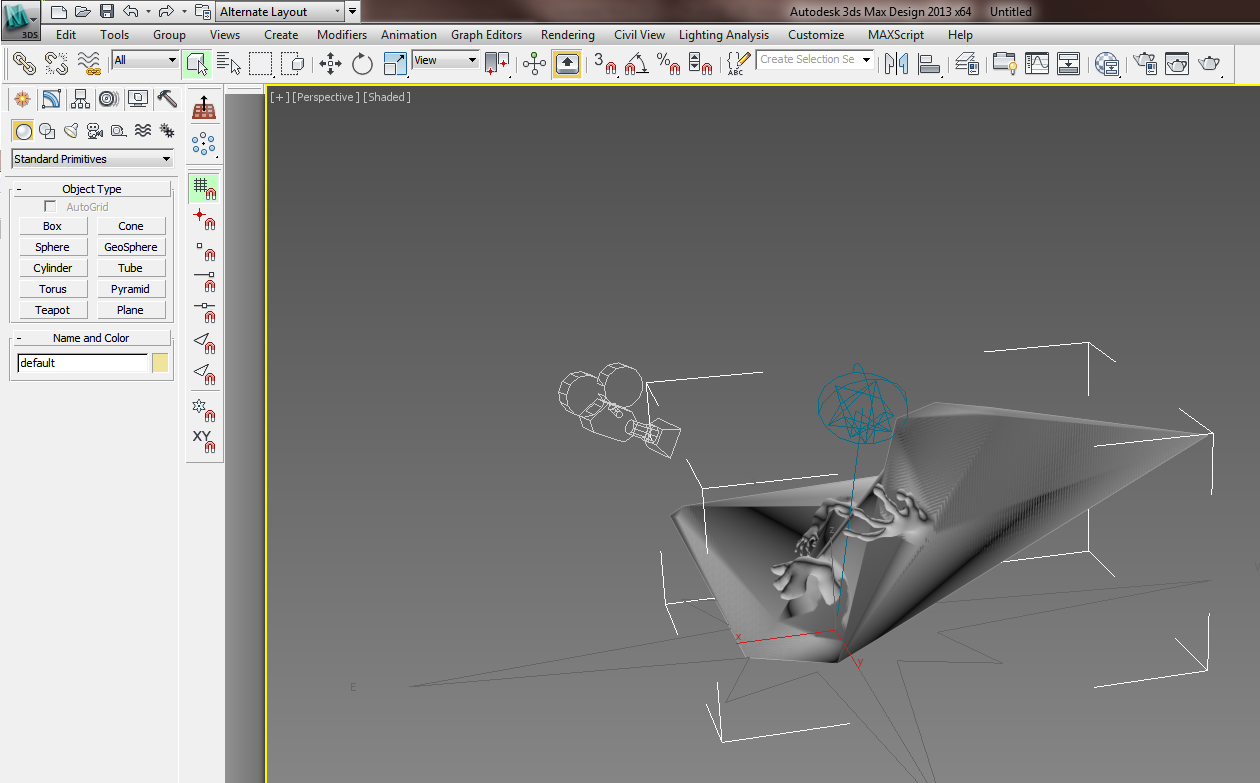
 8) Now import your Revit or Civil3D models and create your animations…

More info:
ASTER Global Digital Elevation Map

via

Infraworks Interference Checking using drive command above pipes:

On a related note: you can use AutoCAD GEO command to grab coordinate data

  • operates in layers

Another link about using Infraworks:

http://translate.google.com/translate?u=http%3A%2F%2Fwww.cadstudio.cz%2Fism&hl=en&langpair=auto|en&tbb=1&ie=windows-1250

I’ve always felt that the Floor tool in Scan to BIM is a bit lacking – rather than analysing and deforming an existing Floor element, I want it to work like the Topo tool (just select a bunch of points and decimate).

Well, now it can (sort of).  Like this:

  1. Use the Scan to BIM topo tool to make temporary topo “Floors”
  2. Then use the Topo to Shape Edited floor macro from Boost Your BIM

Sometimes, What Revit needs is for you to put two workflows together to solve a problem in the most efficient way…

I recently posted about converting Topography to massing forms using a somewhat “manual”, yet lofted and smooth, method:
Convert Revit Topography into Massing Forms

Harry provides some code to do a similar thing with triangulated flat faces over here:
Read the whole post with macro code

Heads-up via:

Have you ever wanted to rationalise your Topography as a Massing form, perhaps so you could use Divided Surface and panelization tools on the topo?

Here is one method:
  1. Make a Site family with a vertical model line and height parameter (see sample file at end of post)
  2. New Project – Make a Toposurface (or existing project with Topo)
  3. New in-place Mass
  4. Place the Site family on the Topo in one corner – it will detect the Topo and host itself to it, even though you are in the Massing environment
  5. Copy a certain number of times in X direction.  Basically, you are forming one part of a grid sampler…
  6. Make a new Adaptive with the same number of points as step above.  I made a 20 point adaptive.
  7. Select all the points, make sure they are Adaptive, Spline through Points
  8. You now have a 20pt Model Line spline… Load into Project
  9. In Massing environment, place the 20pt component by clicking on the very top of the vertical Model Lines from the Site family (as you place it, the points will change to a smaller point size to show it is “living” on the top of that line)
  10. Now, select the whole row of Site families and the 20pt component and copy it along the other planar axis (this is the other part of the sample grid mentioned in step 5)
  11. As the elements are copied, the Site families will host themselves to the Topography, and the Spline will adjust accordingly
  12. Now, select all of the spline families and Create Form!
  13. You can adjust how close to the original site the Massing form is by using the height parameter of the Site model line family
This method could be used in conjunction with the Tree randomizer here.
The image shows the sample surface above, and the original Toposurface below.
The only limitation I found was that if the form is “flat” at some point, the Create Form may not work.  However, if each Spline does vary up and down, it should work ok.

Download the add-in:
Topo From Lines | Autodesk Revit | Autodesk Exchange Apps

Update it:
Use this files in this ZIP to replace the files installed in C:ProgramDataAutodeskApplicationPluginsTopo From Lines.bundle
http://gdurl.com/i2vu

Read the post:
Topo From Lines now available on the Autodesk App Store | Boost Your BIM – making Revit even better

Heads-up thanks to Belinda Thompson

Oh, but if you want a super high resolution contour import, check out:
What Revit Wants: Using Civil3D to increase your Topography resolution in Revit

I previously posted about CADtoEarth at:
https://wrw.is/2012/08/quickly-add-google-earth-site-context.html

Although some people have struggled to implement it or understand how it works, I still like it as a quick way to import Google Earth topography as site context.  The new version is on Exchange at:
http://apps.exchange.autodesk.com/RVT/en/Detail/Index?id=appstore.exchange.autodesk.com%3acadtoearth%3aen

Video:

via email:
We, at AMC Bridge LLC, are excited to announce availability of new version of CADtoEarth for Revit the application that allows for seamless integration between Revit and Google Earth.

The CADtoEarth 2.0 add-in now allows users to create personal accounts on the CADtoEarth web application and provides individual control over the visibility of uploaded data.

We continue improving our applications, so please, dont hesitate to contact us at contact@amcbridge.com if you encounter any problems with the new version, or have any enhancement requests.

Yeah, Revit topo tools aren’t that great.  Why don’t we try exporting to a sculpting tool like meshmixer, and see if we can make it work?

Let’s start with a simple Revit toposurface.

Export to Max by using Suite Workflows – 3ds Max Design Exterior Rendering

Once in Max, export selected (the toposurface) to OBJ using the Mudbox preset.

Open meshmixer (now at version 08).  File – Import the OBJ.  Start playing around with it, using the brush tools to smooth or warp the site.  You may need to ‘scale’ up your active tool by using the middle mouse button to see real results.

I added some body parts to the site:

Export to OBJ from meshmixer.

Back in Max, select the previous surface object.  Then Import, select the new OBJ you just made.

Now, export selected the new OBJ (with morphs) to a DWG file.

Import the DWG in Revit.  If you haven’t gone too wild, you should be able to use Auto – Center to Center option effectively.

Finally, Revit won’t like this import very much – it probably won’t find points to make a surface.  You will need to round-trip this DWG import by exporting out to DWG from Revit and then importing it back in again.

The ’round tripped’ import symbol can be used to generate the Toposurface, now morphed:

You may also be interested in:
Freeform and organic modelling from MeshMixer to 3ds Max to Revit

Basically, if you have one site toposurface, and you cut it with pads in different phases, then an ‘outline’ around every single pad appears in the creation phase of the toposurface (they affect the topo backwards in time).  It looks ugly …  Additionally, there will be ‘holes’ cut in the toposurface for the pads.

I recently handled this by making a Design Option Set for Topography, then for each Stage / Building Option combination, I added the entire site Toposurface.  From here, I could use model groups to transfer pads between the different options / phases, while still retaining their size and position and editability.  It was a pain to set up, but once configured properly (with views etc), it seems to work ok.

The most ‘logical’ way to configure it would be:

  1. Make a Design Option Set
  2. Make an Option called ‘Existing’.  Add your original / untouched site topography here.
  3. Duplicate the Option, call it Stage 1.
  4. Make all the Stage 1 pads, then group them.
  5. Duplicate Stage 1 topography option, call it stage 2 (the grouped pads will come through).  Add additional pads in Stage 2 option, then group Stage 2 pads and the Stage 1 pad group (forming a nested group.)
  6. Rinse and repeat

I never said being a Revit pro would be easy.

You can read about the problem at:
Re: Building pads don’t seem to respect phases. – Autodesk Discussion Groups