From IMAGINiT Technologies Support Blog:
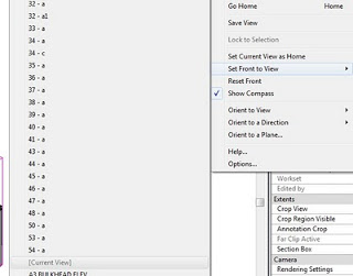
We can add a modifier to the export dialog box for the items we want to adjust, make sure that you also do this to the sub-categories of the element also, and select the Phase Created modifier and add it to the list, in the separator space, add the separator type you want to use…this will give us
something similar to the following in the cad file:  A-DOOR-Existing

Read more at:
Revit Export: How to Export Phases to the Correct Layer – IMAGINiT Technologies Support Blog

Have you ever wanted to control the text on your Sections, even forcing the text to be rotated / aligned with the Section Line itself?  If so, check out the information and links below.

From Oliver Langwich blog:

Problemstellung
Thomas had in his blog at that time solved the problem so that it creates different types of families in the project and appropriate types of sectional views to choose from are issued.
After last weeks I have id delve into the topic of “Nested Labels” and aligning tax and labels, I just had to try again looking and if it does not yet have a way to control the labeling of an angle parameters.
And it goes Smiley !
Although one must still interface types to create and assign an icon, but I have not in the family and setting up elaborate and symbol labeling parameters, provided with a visibility parameter, create family types, etc.
The following three pictures you see above the normal average always labeling, including the angle of parameters.
30-07-2012 15-59-43 30-07-2012 15-59-59 30-07-2012 16-01-01

German link:
http://revit-family-planner.blogspot.com/2012/07/schnittpfeile-reloaded-oder-steuerung.html

Extra / similar information:
Google Translate
of
http://revitde.blogspot.com.au/2011/03/revit-tutorial-schnittpfeil-und.html

What is the U-Value?  It is:
Also known as the U-factor or coefficient of heat transmission, a measure of the rate of non-solar heat loss or gain through a material or assembly. U-values gauge how well a material allows heat to pass through.
http://www.daviddarling.info/encyclopedia/U/AE_U-value.html

autodesk.de recently carried a detailed post on formulas related to the U-value.

Read more at:
Google Translate
of
http://www.autodesk.de/adsk/servlet/pc/item?siteID=403786&id=20378691

Summary

To get the U value of a wall structure, add the sum of the heat transfer coefficients for the wall types specified thermal resistance R T by this value to be used as a divisor.

With walls so:

U = 1 / (Rt (from Revit) 0.17 (K · m) / W)
formel_03

Thanks to one of our readers, we have a solution for the schedule precision problem described here.

The comment below the lines gives the formula to convert an Area into a rounded number in a schedule, and the totals work!  Thanks Максим Ашихмин.

Type: Number

round(Area / 1 м² * 100) / 100 – rounding to 2 decimal place
round(Area / 1 м² * 10) / 10 – rounding to 1 decimal place

My previous post:
What Revit Wants: Area Calculation Totals – Rounding and Precision

Daryl Gregoire posted about this recently and I found his post very helpful.  In the past, if the checkbox was grayed out to ‘Create New Local’, I would just manually copy the file to my C: drive, append my username to it, and then open it that way.  This is ‘old school’ Revit, before the automated local file creation became available.  However, Daryl’s fix is better than my workaround…

Why is the checkbox not available?
you are NOT using the same version of REVIT that was used to create the Central file

How to fix it properly?
open the file, upgrade it to your version of REVIT (done automatic) then ‘save as’ the file and click the ‘Option‘ button in the Save dialog box and tick the option for ‘Make this a central file after save‘.

Read more:
REVIT Rocks !: REVIT – My Create New Local is Greyed Out

EDITSteve posted about another cause for this problem, and he gives some wise advice along the lines of “before you upgrade, think about the consequences…”  Check out his post:
Revit OpEd: Can’t Alter Create New Local Selection

FM, or Facility Management, is sometimes thought of as the sixth dimension of BIM, or 6D BIM.

Mario Guttman, creator of Whitefeet tools, reposted an interesting video / case study by David Mettler showing a potential workflow from Revit into an FM scenario using MySQL:


The process:  “I exported the Revit tables out to Access using the DBlink. From Access I had to setup a ODBC export using SSH Tunneling to get the remote host to show up as a  localhost. It took a lot of time to figure out the connection issues get the data across to MySQL. Once I got the bugs work out on the ODBC connection it’s a piece of cake post the information into MySQL. I used phprunner with the SSH Tunnel to create the pages.”
via
Revit FM Tool | WhiteFeetTools

The goal of this Preview Version of “SOFiSTiK Reinforcement for Autodesk® Revit®” is to enable the productive design of 3D reinforcement with Autodesk® Revit®. This particularly includes the creation of 2D plans and steel schedules.
via
SOFiSTiK AG – Finite Elemente & CAD Software f�r den Ingenieurbau: LabsReinforcement

Register / download link

Heads up:
http://bimblog.typepad.com/autodesk_bim_blog/2012/08/sofistik-bewehrung-f%C3%BCr-revit-2013-als-labs-version.html

The problem – you want to subscribe to an online newsletter, but they don’t offer an RSS or Atom feed.  You don’t want to disclose your personal email address.

You can use the following service to set up a ‘bridge’ between a nominated email address and an RSS feed.  Then you can simply subscribe to the RSS link that the you are provided with:
Emails to RSS Forwarding

It takes a little bit of setting up, but it does solve the specific problem described above.

There are a few freely available applications for AutoCAD that allow it to do some powerful spline editing – tools we don’t have in vanilla Revit just yet.  You can use the tools below to do some line operations in AutoCAD and then Link / Import the resulting elements into Revit:

Splines to Polylines
Download VLX from page below and use APPLOAD in AutoCAD to load it, then SP2PL to run it:
http://www.cadforum.cz/cadforum_en/download.asp?fileID=1488

Polylines to splines
Copy / paste the script from the page linked below into a text file, then save as pl2sp.lsp
APPLOAD in AutoCAD, then PL2SP to run it
Here is a routine that allows you to turn a “Fit Curve” Polyline into a Spline…
AutoLISP: Polyline to Spline | AutoCAD Tips: