Ever had that annoying problem of your entire dwg showing up in Section Views, regardless of where it is cut? If so, check out this tip from Chad at Revit KB:
…if you link the DWG into an In-Place Mass instead, then when the section cuts through the Mass/DWG it will only show just the elements which are being cut by the section.

when placed inside a Mass, that Mass can then be Phased which also means the DWG inside it will too.

via
https://plus.google.com/app/basic/stream/z12zslgqpmqedbufj22wxlrybve1xpb0i

The View “Discipline” setting in Revit is a high level visibility control that can have some significant consequences on how a view actually looks. Amongst other things, it works as a high level switch for Hidden Lines.

As the online Help demonstrates:
In view properties for 2D views and 3D views, set the Show Hidden Lines parameter to By Discipline to display hidden lines based on the assigned discipline of the view.

For all views, the default value for Show Hidden Lines is By Discipline, with the following results:

  • If Discipline is set to Architectural or Coordination, do not display hidden lines.
  • If Discipline is set to Structural, show hidden lines.
  • If Discipline is set to Mechanical, Electrical, or Plumbing, show hidden lines.

The By Discipline value also ensures that the view displays hidden lines specified using the Show Hidden Lines by Element tool of the View tab.
Help: About Hidden Lines and View Discipline

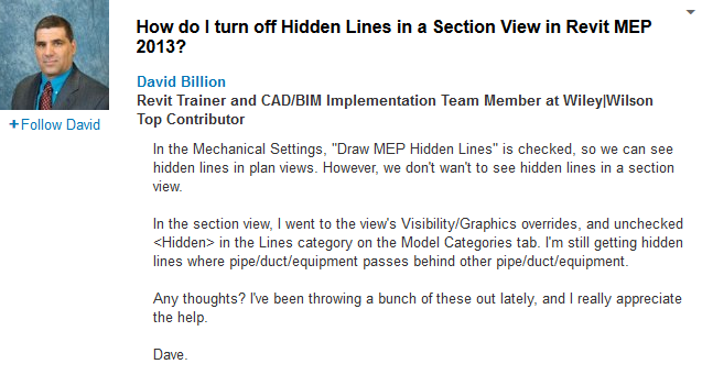
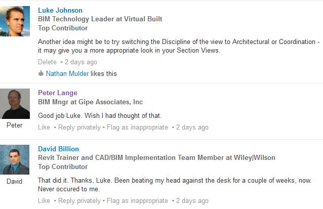
Here is part of a recent discussion in the BIM + Revit MEP group on LinkedIn, where we see David is trying to hide Hidden Lines in a Section View in Revit MEP:

Some more pieces of the View Discipline puzzle:
Determines how discipline-specific elements display in the view. You can also use this parameter to organize views in the Project Browser.

  • Architectural: Displays all model geometry from all disciplines.
  • Structural: Hides non-load-bearing walls in the view and shows elements whose Structural parameter is enabled.
  • Mechanical: Displays architectural and structural elements in half-tone, and displays mechanical elements on top for easier selection.
  • Electrical: Displays architectural and structural elements in half-tone, and displays electrical elements on top for easier selection.
  • Plumbing: Displays architectural and structural elements in half-tone, and displays plumbing elements on top for easier selection.
  • Coordination: Displays all model geometry from all disciplines.

Help: View Properties

and
If you see an entire category of halftoned objects that are not set to display as halftoned (see About the Visibility and Graphic Display Dialog), try changing the view discipline. The Discipline setting determines how different object categories display in discipline-specific views. Also, select Coordination to show all object lines as solid without halftones. See View Properties.
Help: Common Issues with Visibility and Graphic Display

For more detail on View Discipline implications, check out:
REVIT Rocks !: REVIT View Discipline Explained – Kind of
Revit OpEd: View Discipline

(I found the above posts using my custom Revit Master Search engine) 

My somewhat involved workaround for this in the past has been:

1 – Make a thick wall type (like 1m or more)

2 – Draw these walls very ‘tall’ (above and below building vertical extents) around your property lines, such that the wall starts at the Property Line and the thickness protrudes away from the Property Line

3 – Use View Templates with a Filter to override that wall type’s Cut Lines to dashed or dash-dot (whatever you want to see in Sections / Elevations)

4 – When cropping your Section / Elevation View, just crop it in the middle of the ‘thick wall type’ – thus only showing the edge that coincides with the Property Line

5 – Use a Design Option with a blank primary, and in a secondary option put these ‘boundary walls’ – so that they are invisible by default in all views (you could also use hidden Workset). Turn them on selectively using View Templates.

The advantage is that this method always works, even when Sections / Elevations are cut oblique to the Property Line.

Its a fairly old method, and I can’t recall exactly which forum I heard it on, probably AUGI…

Have you ever wanted to control the text on your Sections, even forcing the text to be rotated / aligned with the Section Line itself?  If so, check out the information and links below.

From Oliver Langwich blog:

Problemstellung
Thomas had in his blog at that time solved the problem so that it creates different types of families in the project and appropriate types of sectional views to choose from are issued.
After last weeks I have id delve into the topic of “Nested Labels” and aligning tax and labels, I just had to try again looking and if it does not yet have a way to control the labeling of an angle parameters.
And it goes Smiley !
Although one must still interface types to create and assign an icon, but I have not in the family and setting up elaborate and symbol labeling parameters, provided with a visibility parameter, create family types, etc.
The following three pictures you see above the normal average always labeling, including the angle of parameters.
30-07-2012 15-59-43 30-07-2012 15-59-59 30-07-2012 16-01-01

German link:
http://revit-family-planner.blogspot.com/2012/07/schnittpfeile-reloaded-oder-steuerung.html

Extra / similar information:
Google Translate
of
http://revitde.blogspot.com.au/2011/03/revit-tutorial-schnittpfeil-und.html

This is a subtle change that you may have missed.  In Revit 2011, we had to access the ‘Section Tag’ properties through the Manage tab on the Ribbon (which was a bit annoying).

However, in Revit 2012 we can access the Section Tag properties directly from the properties of any Section that we have selected!  See images below:

The old way

Click on the ‘dots’ to access the Section Tag properties

This definitely allows for an improved workflow.  It is a faster and more intuitive way to change the properties of Section Tags.

For some of you, this will be old news. However, it is a very important yet not very well known procedure. How do you accurately rotate an existing section view accurately?

Here are the steps:

  1. Draw a reference plane from the ‘tail’ of your existing section to (or through) the head point. The Reference Plan should snap to both of these. This is the current ‘plane’ of your section.
  2. Draw another Reference Plane that is parallel to the way you want the section to face.
  3. Move this new Reference Plane so that it also starts from the tail of the section.
  4. Select the Section.
  5. Rotate. Move the rotation marker to the tail of the section.
  6. Use the two reference planes to accurately rotate your section!

We were given the ‘Slanted Column’ ability when some of the Structural tools were recently incorporated into Revit Architecture. If you have been pulling your hair out trying to place one of these slanted columns in a Plan view (where the tool is greyed out), the answer is simple. Go to a Section, Elevation or 3D View to place them!

You will likely need to set an appropriate workplane to ‘draw’ these slanted columns on.

The Brace tool is also quite cool – have a go at the ‘3D snapping’ capability in the Options bar (try it in a 3D view, obviously).

If you are interested in reading further, check out:

http://revitclinic.typepad.com/my_weblog/2009/04/slanted-columns.html

http://bimandbeam.typepad.com/bim_beam/2009/06/revit-structure-2010-slanted-column-parameters.html