Short version:

  1. Edit View Title Family
  2. Turn on the reference planes in the Visibility / Graphic Overrides, select all three items. 
  3. Rotate these items opposite of what you think to offset the rotation of the view. So if you are rotating the view on the sheet 90 degrees counterclockwise, you have to create a view title with these three items rotated 90 degrees Clockwise. 
  4. uncheck “Keep Readable” under the instance properties of the text labels or Revit will try to make the text read up the page, not down.
  5. Save View Title family and apply it to Viewport Type in project

Long / original version, this idea and steps above taken from this post by IMAGINiT:
View Titles for Views Rotated on the Sheet – IMAGINiT Building Solutions Blog

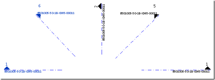
Have you ever wanted to control the text on your Sections, even forcing the text to be rotated / aligned with the Section Line itself?  If so, check out the information and links below.

From Oliver Langwich blog:

Problemstellung
Thomas had in his blog at that time solved the problem so that it creates different types of families in the project and appropriate types of sectional views to choose from are issued.
After last weeks I have id delve into the topic of “Nested Labels” and aligning tax and labels, I just had to try again looking and if it does not yet have a way to control the labeling of an angle parameters.
And it goes Smiley !
Although one must still interface types to create and assign an icon, but I have not in the family and setting up elaborate and symbol labeling parameters, provided with a visibility parameter, create family types, etc.
The following three pictures you see above the normal average always labeling, including the angle of parameters.
30-07-2012 15-59-43 30-07-2012 15-59-59 30-07-2012 16-01-01

German link:
http://revit-family-planner.blogspot.com/2012/07/schnittpfeile-reloaded-oder-steuerung.html

Extra / similar information:
Google Translate
of
http://revitde.blogspot.com.au/2011/03/revit-tutorial-schnittpfeil-und.html

Most of us use the old Reference Line with angular dimension method to control rotation in our vanilla Revit families.

However, Marcello Sgambelluri has posted three alternative methods to control rotation and angular dimensions, with full step-by-step instructions, at his blog Simply Complex.

Marcello says:
I have given three rotation rig methods that do not use the angular dimension parameter in these last two postings. These methods are the Ride the Rail method, the Open Reference Circle method, and the Revolve method.

So the method names again are:

  1. Ride the Rail
  2. Open Reference Circle
  3. Revolve

Read more about them at:
Simply Complex: ROTATION RIGS THAT DO NOT USE THE ANGLUAR DIMENSION PART 2
and
Simply Complex: ROTATION RIGS THAT DO NOT USE THE ANGLUAR DIMENSION

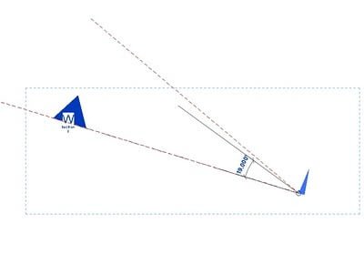
For some of you, this will be old news. However, it is a very important yet not very well known procedure. How do you accurately rotate an existing section view accurately?

Here are the steps:

  1. Draw a reference plane from the ‘tail’ of your existing section to (or through) the head point. The Reference Plan should snap to both of these. This is the current ‘plane’ of your section.
  2. Draw another Reference Plane that is parallel to the way you want the section to face.
  3. Move this new Reference Plane so that it also starts from the tail of the section.
  4. Select the Section.
  5. Rotate. Move the rotation marker to the tail of the section.
  6. Use the two reference planes to accurately rotate your section!