“new Download Section is now available on revitforum.org“
Tag: free
Ever wanted to fillet between 3D edges in Revit? Some of the limitations of 3D modelling in Revit were discussed at RTCAUS, so I thought I would try a little ‘tech demo’ of sorts…
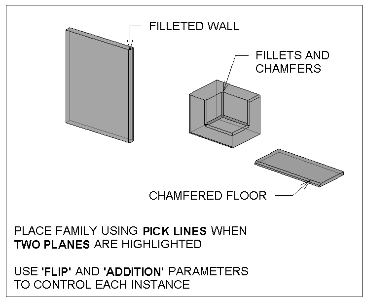
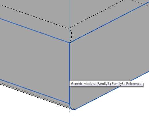
Revit 2012 gives us an opportunity to do some nice things with in-project voids. Below, you see corners of a Wall, Floor, and Generic Model being filleted and chamfered (chamfer is the word we use in Australia for a ‘diagonal’ or triangular fillet).
Basically, I have created two line-based Generic Model families. These are called:
Chamfer line based void and solid family D.rfa (the triangular form)
Fillet line based void and solid family D.rfa (the arc fillet form)
I then load these into a project. When placing these families in 3D, if you place them when two perpendicular planes are highlighted at the same time, you get some nice control. If you do this, Revit places the item ‘on’ one plane, and ‘aligned’ to the other plane.
These families can do two things to the edge – cut a void, or add a fillet. You use the ‘Flip’ Yes / No parameter to get it in the right spot, and the ‘addition’ Yes / No parameter to choose if you want the item to show the ‘fillet’ solid part.
Feel free to download the example and have a play with it. Sure, there are some limitations to this method, but some of you may find it useful.
Do you have a more elegant solution to this? Feel free to comment…
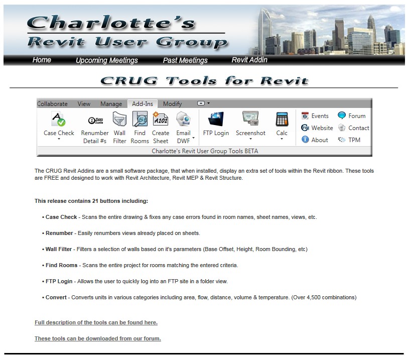
This release contains 21 free features including:
• Case Check
• Renumber
• Wall Filter
• Find Rooms
• FTP Login
• Convert
Here are some direct links to the setup files:
Revit 2012 – Windows 7 and Vista
Revit 2011 – Windows 7 and Vista
Here is a link to the main page for these tools:
Charlotte’s Revit User Group
Here is “an a-z playlist of the revit architecture beginner [highway] course” from the UQARCHCAD Youtube channel.
Also see:
Cool post from Steve about Tekla BIMsight – free download link here.
Revit OpEd: Tekla BIMsight – Free divided by Free is still Free!
Steve Stafford is a pillar of the Revit community. There are some great free downloads at his site, AEC Advantage.
Check out the downloads page:
http://www.aecadvantage.com/links2
There is a great document on Revit Roles in a practice, and a cool example of how to handle non-perpendicular Grid Display. You can also find a Door Family tutorial handout from AU.

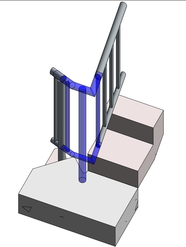
Stairs and railings in Revit can be extremely frustrating.
In fact, I’m often annoyed that I can’t even model a Railing in-place, as the Railing category isn’t available for in-place families!
So, how do you make an unusual ‘custom’ railing connection work?
In 10 steps:
- Create a 3D view with section box around the connection you would like to resolve
- Export this 3D view to a DWG file.
- Create a new Generic Model family.
- Import the 3D DWG.
- Using the context you have now imported, model the rest of the baluster / railing connection. I recommend that you use Reference Lines and then create Sweeps using ‘Pick Lines’.
- After you have modeled the custom 3D geometry in the Generic Model family, create a Baluster Post family.
- Load the Generic Model family into the Baluster Post family.
- Load the Baluster Post family into the Project.
- Apply your new custom Baluster Post to the Start / Corner / End post of the Railing you are trying to correct.
- In the Baluster Post family, rotate and move the Generic Model family around until it is in the right place and reload into the Project.
For a sample project showing one of these connections, open the following file:
For a sample Baluster Post family, download the following file:
I found this ‘section box’ technique in the book Mastering Revit Architecture 2011.