Check out this list – you won’t regret it:
Scott Hanselman’s 2014 Ultimate Developer and Power Users Tool List for Windows – Scott Hanselman
186 pages long, download at:
http://www.certh-india.com/software-cd/softwares/navisworks/texte/bfts/Roamer_userguide.pdf
Download:
complete Revit MEP project setup, using this MODULE
The guide includes detailed step-by-step processes, and screenshots.
Original post:
http://forum.indivirev.com/?p=580
via
Revit MEP (LinkedIn Group)
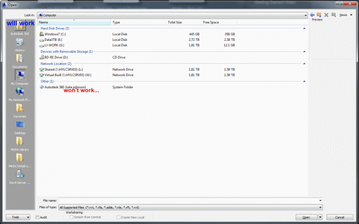
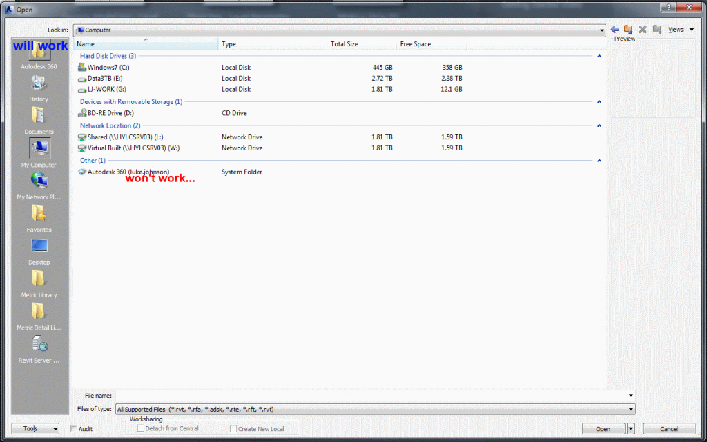
When Autodesk 360 is installed (current version is 4.7.0.802), it creates a “special” Autodesk 360 link that lives directly under My Computer. Additionally, certain Autodesk applications can directly access Autodesk 360 using a special link.
However, some current Autodesk applications do not seem to have direct access to Autodesk 360 via any special “links”. What to do?
- In Windows Explorer, open the special Autodesk 360 link (which has your Autodesk login name appended), and then
- right-click on a subfolder and
- select Open in New Window
- Now, click in the address bar and the “location” should be revealed…
In my case, it was:
C:UsersLuke JohnsonAppDataLocalAutodeskAutodesk SyncCloudluke.johnson
So, yours should be:
C:UsersyourWindowsUsernameAppDataLocalAutodeskAutodesk SyncCloudYourAutodeskLogin
I know its not rocket science, but you can now use this path to access Autodesk 360 from any application.
You could also add this address to your Revit My Places list, and then modify the name of it in the Registry to be Autodesk 360 🙂
This is the current tree node for editing Revit 2014 My Places names:
HKEY_CURRENT_USERSoftwareAutodeskRevitAutodesk Revit 2014ProfilesAllAnavDialogs
Hypothetically, the above method allows you to Link a CAD file from your local sync of your online Autodesk 360 data directly into a Revit project.
From the description by uploader Alex Neihaus on Youtube:
the screens shown were pre-release versions of the product, the music was an original composition (not stock music) and at an AIA convention, Revit rented a 20,000 watt stereo system and mounted it in a 16-foot glass tower to overpower the competition. The video was produced on a then massively sophisticated Avid system with something like 54 layers in Watertown, MA.
Here is the promo video:
I extracted some screenshots out of it, and here they are – prerelease Revit!
Heads-up:
https://twitter.com/RTVTools/status/436440176848416768
From Mark Wieringa in comments on my previous post:
Hi Luke,
There’s a quick workaround for your problem. You’re able to hack tags for certain categories to show the Level that the elements have been created on.
What you need to do is open a ceiling tag, then make the label for Level. Copyclip the label and delete the original, then change the category to for instance floors and pasteclip.The label will still refer to the Level parameter and will report it for categories that have the parameter available.
Greetings
Mark Wieringa
Great tip! As proof of concept, please see files for download at:
https://drive.google.com/file/d/0B1dGdRkpk2beVVZNSGU4UlRrcE0/edit?usp=sharing
Over the years, there have been a few attempts at modelling a Mobius Strip (or band) in Revit. The BIM Troublemaker had a go back in 2010, Chad also tried in the comments, and The Proving Ground showed a method with RevitPythonShell. Another guy tried using a massive rig on Youtube (skip to 7.55).
For me, the conceptual analysis of this problem goes back to a fundamental question – is a piece of paper a surface, or a solid? It is really both, depending on the accuracy of the equipment you are using to measure thickness. When it comes to modelling it in Revit, I prefer to think of it as a surface – something with no inherent thickness, just a piece of stuff that we twist 180 degrees and try to stick back to itself.
Similarly, I’m more concerned with making the Mobius Strip out of one piece (one “Create Form”), rather than two pieces. And I’m not too worried about seeing a single seam line – even the piece of paper Mobius Band has visible sticky tape 🙂
So in my example, I created a form derived from nested line families (parametric band width) that are hosted on Reference Points. These Reference Points are driven by the Normalized Curve Parameter and Rotation Angle to set up a slowly twisting rig for the Create Form. The Reference Points live on a Spline, that was placed on a Divided Path based on Arc / Circle segments. This gives me two things – a simulated rig-driven “circle” that is actually a Spline (that has a parametric radius), and the ability to add a “Closer” parameter to push the two ends of the band together.
Hey, I know its not perfect, but it was a bit of fun! Oh, and did I mention that the Wall by Face tool in Revit will happily generate a wall from this family in a single click?
You can download the example here:
https://drive.google.com/file/d/0B1dGdRkpk2beZ0FaMDIxai15aUE/edit?usp=sharing
There have been various attempts over the years to create a true BIM portal, with links to all relevant documentation. Have you checked out CODEBIM? The reports page is pretty impressive list of BIM documents …
Heads-up:
Hefty collection of useful docs > #BIM Reports | CODEBIM: Collaborative Design Education using BIM http://t.co/jJqELoA1Zx h/t @case_inc
— Elrond Burrell (@ElrondBurrell) February 19, 2014
Quote:
“The Mechanical Contractors Association of America (MCAA), in a tripartite project with the Sheet Metal and Air Conditioning National Association (SMACNA) and the National Electrical Contractors Association (NECA), has published Achieving Spatial Coordination Through BIM – A Guide for Specialty Contractors. Dubbed “the Guide”, the publication was conceived, developed, and published to help MEP contractors negotiate one of the most challenging issues in the modern construction industry: how to best reconcile and incorporate leading edge technologies and processes into their projects’ spatial coordination efforts. Click here to get more information and download the Guide.
Lessons learned by early BIM adopters like MCAA BIM Committee Chairman Steve Shirley (University Mechanical & Engineering Contractors) and fellow members of MCAA’s BIM Committee members were combined to develop a set of best practices and proven, how-to information. The result is a guide that will help contractors better navigate this complex issue and make more informed business decisions about spatial coordination and BIM. It will also serve as an educational resource for their employees who must act on those decisions.”
http://www.mcerf.org/news/2013/mcerf-funds-landmark-bim-publication
…
The purpose of this Guide is to:
- Provide MEP contractors with a roadmap for implementing spatial coordination in their businesses;
- Identify factors MEP contractors should consider when adopting BIM technologies;
- Help MEP contractors align their spatial coordination processes with industry best practices;
- Enable MEP contractors to critically evaluate emerging BIM and spatial coordination software solutions and select the solutions most suitable for their own work;
- Promote collaborative and fair contract language; and
- Increase MEP contractors’ profitability and reduce customers’ costs by implementing best practices that increase prefabrication, optimize systems installation, minimize or eliminate rework, shorten construction schedules, reduce waste, and produce a better result.
Download at:
http://www.mcaa.org/mepguide/M29PDF.pdf
Authored by Dave Quigley:
www.linkedin.com/pub/dave-quigley/0/66a/856
Thanks to Cindy James for referring me to this document.