You may have to clean up or fix up a mechanical Revit model where the Duct Fittings have become out of sync with the system they are supposedly connected to. For some reason, the System Classification and System Type may not match up. There are at least two ways to fix this:

  • drag and rejoin one of the connectors to the correct system. The system should regenerate.
  • Cut one of the problem elements, then Paste Align – Same Place. After this, you will need to use Connect Into to get the element connected with the system. You might find that doing this on one Fitting will force a regeneration on the entire system, fixing all Duct Fittings with this problem at once.

I have put together a quick screencast for each of these methods:


If you have another way of fixing these problems, feel free to comment. Thanks!

To change the System Type for the connected run, Tab-select until you have the System, then change the Type. You can also change the name here.

To completely undefine pipes, tab-select the system, then delete it. Pipes will become undefined. Start Draw Pipe command from one end and a new name will be automatically created. Apply System Name and System Type as above.

via
Changing Pipe from One System to Another

and here is how you can break systems up by using a custom family with multiple connectors:

via
Breaking up Pipe Systems

Note on upgrading: we discovered an interesting thing in the Design Office recently. When upgrading Revit 2013 files containing Systems (in this case Pipe) to Revit 2015, it is highly advisable to install the latest update (preferably R2, which is roughly equivalent to Update 4) prior to upgrading. If you use the ‘initial release’ version of Revit 2015, it will come up with lots of warnings if you have systems with duplicate names. However, it appears that the R2 version will automatically go through and un-duplicate the System names for you, making them all unique. Obviously, there may be a situation where this is not desirable (tagged systems linked to quantity takeoff or something), but for the most part it is nice to have all of those errors / warnings fixed during the upgrade to 2015.

Also some related into at:
Re: Pipe System to same Pipe System of a different… – Autodesk Community

UPDATE: Tip from Jim in the comments regarding Revit and Sysque, and exploding systems…
In 2015 REVIT-Sysque if you are having the problem where when you change pipes to a certain system more pipes than you thought (sometimes all) of the pipes change to one system or another.

SOLUTION: Pick a pipe, a tab opens up which says “piping systems” pick that tab. It highlights the whole system the pipe you have selected is apart of. It may consist of supply and return piping. This is where you can explode the system. DO IT. You can then change what pipes you want change to a particular system and not have to redraw anything. jim badiali 

Check out the survey results from Design Master Software – interesting that 2/3 using Revit over AutoCAD:

And how does MEP industry take-up of BIM compare with what was expected in 2011?

As with any such survey, its value must be regulated by the question:  
“Do the survey respondents represent an accurate cross-section of the industry itself?”

Read more:
MEP 3D-BIM 2014 Survey Results – Design Master Blog

The View “Discipline” setting in Revit is a high level visibility control that can have some significant consequences on how a view actually looks. Amongst other things, it works as a high level switch for Hidden Lines.

As the online Help demonstrates:
In view properties for 2D views and 3D views, set the Show Hidden Lines parameter to By Discipline to display hidden lines based on the assigned discipline of the view.

For all views, the default value for Show Hidden Lines is By Discipline, with the following results:

  • If Discipline is set to Architectural or Coordination, do not display hidden lines.
  • If Discipline is set to Structural, show hidden lines.
  • If Discipline is set to Mechanical, Electrical, or Plumbing, show hidden lines.

The By Discipline value also ensures that the view displays hidden lines specified using the Show Hidden Lines by Element tool of the View tab.
Help: About Hidden Lines and View Discipline

Here is part of a recent discussion in the BIM + Revit MEP group on LinkedIn, where we see David is trying to hide Hidden Lines in a Section View in Revit MEP:

Some more pieces of the View Discipline puzzle:
Determines how discipline-specific elements display in the view. You can also use this parameter to organize views in the Project Browser.

  • Architectural: Displays all model geometry from all disciplines.
  • Structural: Hides non-load-bearing walls in the view and shows elements whose Structural parameter is enabled.
  • Mechanical: Displays architectural and structural elements in half-tone, and displays mechanical elements on top for easier selection.
  • Electrical: Displays architectural and structural elements in half-tone, and displays electrical elements on top for easier selection.
  • Plumbing: Displays architectural and structural elements in half-tone, and displays plumbing elements on top for easier selection.
  • Coordination: Displays all model geometry from all disciplines.

Help: View Properties

and
If you see an entire category of halftoned objects that are not set to display as halftoned (see About the Visibility and Graphic Display Dialog), try changing the view discipline. The Discipline setting determines how different object categories display in discipline-specific views. Also, select Coordination to show all object lines as solid without halftones. See View Properties.
Help: Common Issues with Visibility and Graphic Display

For more detail on View Discipline implications, check out:
REVIT Rocks !: REVIT View Discipline Explained – Kind of
Revit OpEd: View Discipline

(I found the above posts using my custom Revit Master Search engine) 

So, you have received a RTE or RVT file (along with related CSV lookup tables) and want to upgrade it without getting the “One or more families in this project are missing .csv files” error…

For example, you may download a Piping Template (like this one from AUGI), and it comes with CSV files but you don’t know where to put them? Or you have received some other MEP template file from the wild, and you would like to upgrade and use it?

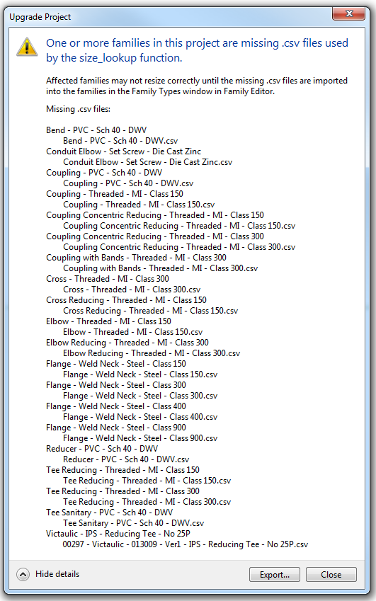
The thing with MEP content is that some of it is based on, or related to, Lookup Tables. These are text (CSV) files that contain type data, essentially making it easy to create and manage types without having to always use the Family Editor to do so. However, if these are missing, you will get an error message when you attempt to open or upgrade a project that needs them:

To fix this, you need to copy the required CSV files into the Pipe and Conduit subfolders of the Lookup Tables folder that matches the version of Revit that you are upgrading TO.

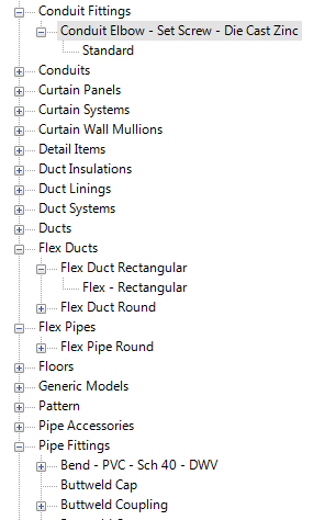
The key Project Browser tree entries are Conduit Fittings and Pipe Fittings:

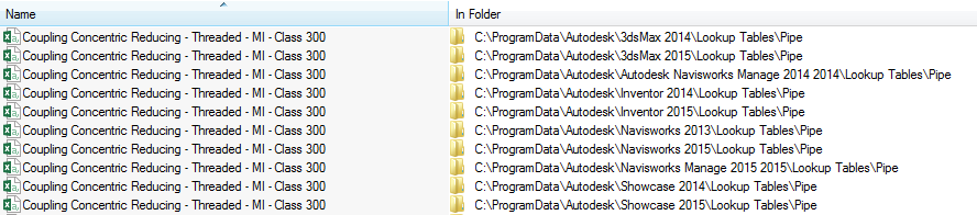
If you have a Suite installed, you may find that these CSV files are duplicated in various locations, to provide support files for 3dsMax and Navisworks. Some of these paths are shown here:

You can browse to the above paths, and start to put together a “consolidated” or “combined” CSV Lookup Table folder, that you may want to maintain in a network location. Once you have collected all of the necessary CSVs, here is how you “install” them:

  1. Determine location to put the CSV files into (usually it will be near your Family Templates folder, a few example paths are provided below)
  2. Create a master folder of all required CSV files (you could maintain a consolidated folder in a network location)
  3. Copy these CSV files to the Pipe and Conduit folder locations (you shouldn’t need to restart Revit).
  4. Open the MEP RVT or template file that you wish to upgrade
  5. Any CSV files that are still missing are the ones you need to find, and put in the Pipe and Conduit subfolders as per steps 1-3.

You could script some of the above steps to aid in deployment.
Revit 2014 Lookup Tables default location:
C:ProgramDataAutodeskRVT 2014Lookup TablesPipe
C:ProgramDataAutodeskRVT 2014Lookup TablesConduit

Revit 2015 Lookup Tables default location:
C:ProgramDataAutodeskRVT 2015Lookup TablesPipe
C:ProgramDataAutodeskRVT 2015Lookup TablesConduit

NOTE: Massive amounts of CSV lookup tables in the default directory may result in slow Revit performance, particularly when starting Revit.

If you want to import Lookup Tables directly into families (and you are perhaps experiencing errors with nested families), this PDF may be of interest.

Finally, you can actually modify Lookup Table location using the revit.ini file, as described here. You could therefore point your Revit installations to a network location containing all of the required CSV files for your firm.

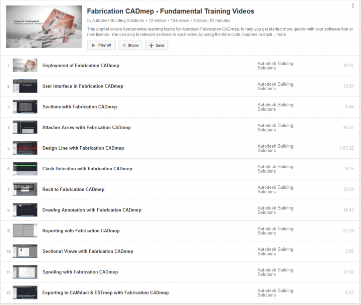
You can download content from Seek and other places online. Sometimes you will find a CSV file, sometimes you may have to export one as per the video below:

There is some related info at:
http://revitoped.blogspot.com.au/2008/10/revit-mep-lookup-tables.html

Feel free to comment if you have any other tips related to Lookup Tables…

Heads-up from Ideate Solutions, originally from Revit Clinic:
tagging the physical wires instead of tagging the device:

  1. draw wires coming off of each connector as small as possible 
  2. (if the wire is short enough, the arrow head will not show up.) You can then 
  3. hide the dot/short line of the wire in the symbology of the family and 
  4. tag it.

via
Ideate Solutions: Revit MEP FAQ – Tagging Families That Have Multiple Connectors

This can be done with AutoCAD MEP 2015, or Architecture, or similar verticals that have the IFCEXPORT command.

  1. Open AutoCAD MEP
  2. New DWG file
  3. IMPORT -> select SAT file
  4. IFCEXPORT
  5. Open IFC in Revit

The advantage of doing this over importing the SAT directly to a Generic Model family is that the IFC method will result in individual forms for each bit of the SAT file. If there are 1200 forms, you will get 1200 families in Revit. This, in turn, will export to Navisworks with this level of element hierarchy (instead of just one big imported SAT element).

This will also result in higher granularity of clashes when using the converted SAT via IFC method (more forms to clash against).

You probably know that you can attempt to explode a SAT in a Revit family, but I find that sometimes unsupported elements disappear using this method… so I like my way via AutoCAD a bit better at this stage.