EDIT Current category guide post:
https://wrw.is/2013/09/new-crowdsourced-and-open-source.html
In Revit, some families have Cut Dominance, some are Cuttable, and some respect various View Range rules in various ways.
These behaviours may further be affected by the Family Template that they were created from, whether they are Hosted or non-Hosted, whether they are Shared or not Shared.
Wouldn’t it be awesome if there was a document that went through each Family Category and described its unique properties! I have asked Autodesk for this before, but to no avail (SR# 1-9298685321 – The help file does not describe the unique properties of each Category).
Andy Milburn shares my feeling on this matter:
… I wish I know where to find a clear explanation of all these rules.
at
Shades of Grey: CUT ! CUT ! CUT !
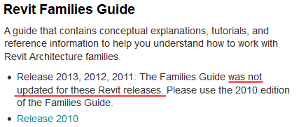
What about the Families Guide?
I may not have all the answers, but I have posted many times about the differences between certain Family Categories. See some links below:
Cuttable vs Non-cuttable Family Category Properties
View Ranges (and TOLERANCES) Explained *REPOST*
Things like –
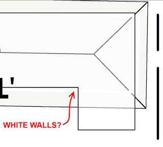
Walls shorter than 6 feet (approximately 1.83 meters) are not cut, even if they intersect the cut plane, and
There are a few categories for which an element located above the cut plane but partially below the top clip is shown in plan. These categories include windows, casework, and generic model. These objects are shown as viewed from above.
Project Family Category Type Instance
which Categories do not have Types, or which Category has Types but no Instances?
Making unhosted components like unhosted Doors and Windows
Create a Component Family with Category set to Walls (or other system family category)
Yes, it is possible.
Plan regions have no effect on Topography – workarounds
buildz: Wall Trimming Method
Cut Dominance in action

 6:12 Vasari Talk 18: Grasshopper to Vasari- Introductions
 5:23 Vasari Talk 18: Grasshopper to Vasari – Jon Mirtschin on Geometry Gym
 9:41 Vasari Talk 18: Grasshopper to Vasari – Hiroshi Jacobs on Chameleon
 10:23 Vasari Talk 18: Grasshopper to Vasari — Tim Meador on Hummingbird.mp4
 12:00 Vasari Talk 18:Grasshopper to Vasari — Nathan Miller on OpenNURBS
 18:25 Vasari Talk 18: Grasshopper to Vasari — Discussion.mp4