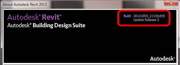
Product Tutorials

Autodesk® Revit® Architecture 2011 Video Tutorials
BIM Curriculum for Architecture, Engineering and Construction Management tutorials

Autodesk and Yale University BIM Symposium

As BIM adoption accelerates throughout the building industry, so does the need for BIM integration into the education curricula of AEC disciplines. This change in the academic environment is quickly becoming a reality. In April of 2010, at Yale University, Phil Bernstein, vice president of industry strategy and relations at Autodesk and lecturer at Yale School of Architecture, along with Yale Professor Peggy Deamer developed and moderated the Yale BIM Symposium: Implications for Architectural Pedagogy. The following videos and proceedings represent some of the several presenters from this informative event.
Phil Bernstein—Welcome and Introduction to BIM DiscussionPhil Bernstein—Implications of BIMPeggy Deamer—BIM’s Pedagogical Placement in AcademiaJohn Messner—Leveraging BIM to Enable the Development of Collaborative KnowledgeJosh Emig—BIM in Integrated Design and Construction EducationDavid Fano—Engaging the Tools: Digital Fabrication

Inspirational Videos

US Department of Energy Solar Decathlon
Autodesk Builds LEED CI Platinum Certified Headquarters Video
Phil Bernstein at AIAS Grassroots Leadership Conference 2009
Change Your World: BIM
Change Your World: Generation Next
Change Your World: Education Community

via
BIM Videos | BIM Workshop

If you have problems with your Revit Filled Region hatch patterns displaying grayscale when they should be black, its probably because Revit thinks that the lines are too close together for the scale of view that you are using.

What Revit wants is for you to increase the scale or spacing between the individual lines of the Filled Region pattern – then it will switch back to black, as it should be.

Using a Model pattern, I was able to observe the pattern go from light gray to black as I changed the scale (spacing) between the lines.

Interestingly, using a Drafting pattern allowed me to put the lines in the Filled Region much closer together…

Some more info at:
RevitCity.com | filled region pattern color changes when drawing scale changes

Many of us were quite disturbed by the 2013 Revit Materials Editor.  Aside from its usability (or lack thereof), it seems to be much slower than the 2012 Materials dialog.  Until Revit 2014 comes around, what can you do to speed up the Materials Editor?

A recent and highly informative post from Aaron Maller (focused particularly on Revit deployment), gives us a few clues:
Switch all the mat lists to text style, no rendered preview, open the Mat Editor and place it next to the Mat selector, then close it. 
Read the whole post here

Have a look at the images below for some ‘hidden’ options:

Appears to be no way to adjust the rendered swatch?
After switching to Appearance aspect, a tiny arrow appears…

We can now adjust this to speed up the Materials Editor.  The above settings seemed to be the fastest
(Pool of liquid / Draft Quality)

We can also completely remove the rendered preview image by dragging the splitter just below it:

Aaron made similar comments in this post on RFO.

In my case (Building Design Suite 2013 / Revit OneBox), the currently in use MaterialUIconfig was at
“C:UsersLukeAppDataRoamingAutodeskRevitAutodesk Revit 2013MaterialUIConfig.xml” 

Upon opening the MaterialUIConfig.xml, you will notice a few settings like:

MaterialBrowser inSceneMaterialViewHeight=”502″ navigationPaneWidth=”241″ isInSceneMaterialPreviewEnabled=”0″ isNavigationPaneVisible=”1″

and

MaterialEditor SplitterPosition=”0″ OGSRenderQuality=”0″ PreviewRenderQuality=”0″ PreviewRenderType=”2″

I would like to see some documentation from Autodesk to clarify what all of these actually do, but you can see the settings I am using.  If you use Notepad++, you can also open MaterialUIConfig.xml, make some changes in Revit, and then when you switch back to Notepad++ it will prompt you to reload the xml – you can then easily see what each change you make in the Materials Browser / Editor actually does.

While familit do have a browser / content manager add-in, this is a paid product (if you are looking for free family browser, check out tools4revit).  However, the family content itself at familit is free:
At the moment familit.com offers 18.000 free families in English, German and French language.

http://lumion3d.com/

You don’t even need to register.  Just go to the following link and start downloading:
familit – Revit Family Library

EDIT Current category guide post:
https://wrw.is/2013/09/new-crowdsourced-and-open-source.html

In Revit, some families have Cut Dominance, some are Cuttable, and some respect various View Range rules in various ways.

These behaviours may further be affected by the Family Template that they were created from, whether they are Hosted or non-Hosted, whether they are Shared or not Shared.

Wouldn’t it be awesome if there was a document that went through each Family Category and described its unique properties!  I have asked Autodesk for this before, but to no avail (SR# 1-9298685321 – The help file does not describe the unique properties of each Category).

Andy Milburn shares my feeling on this matter:
… I wish I know where to find a clear explanation of all these rules.
at
Shades of Grey: CUT ! CUT ! CUT !

What about the Families Guide?

I may not have all the answers, but I have posted many times about the differences between certain Family Categories.  See some links below:

Cuttable vs Non-cuttable Family Category Properties

View Ranges (and TOLERANCES) Explained *REPOST*
Things like –
Walls shorter than 6 feet (approximately 1.83 meters) are not cut, even if they intersect the cut plane, and
There are a few categories for which an element located above the cut plane but partially below the top clip is shown in plan. These categories include windows, casework, and generic model. These objects are shown as viewed from above.

Project Family Category Type Instance
which Categories do not have Types, or which Category has Types but no Instances?

Making unhosted components like unhosted Doors and Windows

Create a Component Family with Category set to Walls (or other system family category)
Yes, it is possible.

Plan regions have no effect on Topography – workarounds

buildz: Wall Trimming Method
Cut Dominance in action

In ye olde AutoCAD days, there were a plethora of ways to mess with your fellow users.  The sheer amount of obscure yet powerful system variables gave endless opportunities for frivolity.

In Revit, not so much.  The system works.  It seems Revit does not want you to prank your coworkers, right?  Here is a little story …

We were having trouble finding a particular Revit link, or more specifically, the walls in a particular Revit link.  So we drew a roof, and the view looked like this:

Ok, so the answer seems easy.  Walls are overriden, right?  Let’s have a look in the View Template:

According to the Visibility / Graphics of Model in the View Template, everything seems cool.  Walls aren’t overridden.  All of the cells look the same, in their default state.

Or are they?

Let’s select the Walls row:

A tiny, almost invisible sliver of white appears under the Project Lines column, while all of the other columns show Override (indicating they are not overridden).

So what exactly is happening?  Let’s click on the Projection Lines override for Walls:

We get very little feedback from Revit as to what is happening until we select the actual row.  Why?  Because the override is set to white!

This is certainly a trap for new, or old, Revit players.  If you read this blog, you are prepared.

If you don’t, you may be pranked by some White Line overrides in the very near future 🙂  Let the shenanigans begin…

I previously posted about Three Ways to go from Grasshopper to Revit.  However, Vasari Talk 18 (uploaded by AutodeskBuilding) shows that there are at least 4.

Learn more by viewing the playlist embedded below:

Or you can choose individual parts to watch here:
Vasari Talk 18 video playlist

What are the 4 ways?

via
Session 18: Grasshopper to Vasari Panel Discussion – WikiHelp

A few words on 3D engines and InterOp from WorldCAD Access:

“For instance, InterOp now directly translates from competitor Parasolid, non-competitor SolidWorks (which uses Parasolid — it’s a complicated relationship), competitor Siemens NX, and non-competitor Catia V6; it reads and writes Dassault’s 3DXML with tesselation. It extracts graphical data from CAD programs like Solidworks, and then display it — although it is not clear to me what this last item means.
OK, now I get it.  “Graphical data” means that the imported 3D model looks just like in the originating CAD system, completed with shading, rectangular boxes at the ends of leaders, arrowheads, and so on.”

Read more:
Live blogging from the 3D Insiders Summit – WorldCAD Access

New Dassault logo via WorldCAD Access