Let’s say you have a Generic Annotation family with about 60 different view states controlled by visibility Yes/No checkboxes. These visibility states are linked to Sheets, and the Generic Annotation families themselves are placed in the Sheet views in Revit. I’m sure you are thinking “why??” at this point, but let’s skip past that part…

Can we drive the Annotation family visibility states based on its ‘host Sheet’ in Revit? Not really.

Can we create a mapping table in Excel, Dynamo-push a single integer value into the Annotation instances based on the host Sheet, and drive the visibility by formula that way? Yep.

Here’s the basic steps:

  1. I used dir and Notepad++ to make the list, one column in Excel for the lookup value (I used Sheet Number), and one for the parameter I want to get and use
  2. This relied on having the Family parameter list sorted Ascending in the Family Editor

  3. The Excel sheet looked a bit like this – notice how the driving parameter is an Integer?

  4. This is the work in progress in Dynamo – getting the Generic Annotation families, matching them up and getting the related Excel integer value

  5. This is the completed dyn, with the push back into the Element Parameter to drive the visibility – see how the string has to get converted ToNumber before pushing into the Integer parameter?

  6. And here is one instance in the project

  7. After running this once, all visibility states are set properly throughout the project

Yet another example of @dynamobim making the Revit-impossible, possible 🙂

    We often work with consultants using Tekla Structures, but we only recently came across the issue of trying to import point clouds into Tekla. The officially recommended workflow is:
    Leica / Trimble scanner — Trimble Real Works — Landxml — Tekla Structures

    But what if we don’t have Real Works? Basically, we want to create geometry from point cloud (which we can make into a massive list of XYZ values in a text file). Sounds like an easy job for Dynamo… and in a way, it is.

    Here is what worked for me:

    1. Import the source point cloud to Recap, decimate to 100mm grids, and remove all values except X,Y,Z (screencast below). This took me from about 19 million points down to about half a million
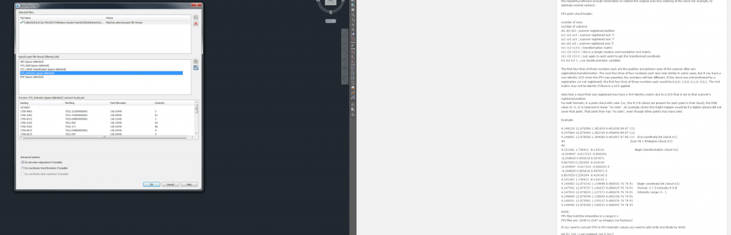
    2. Export from Recap to PTS format.
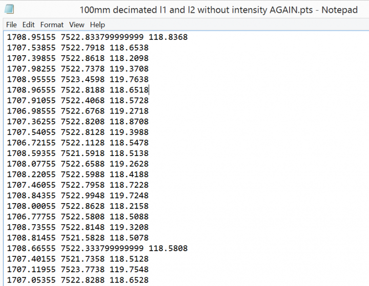
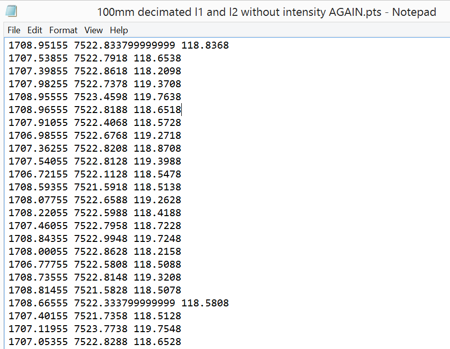
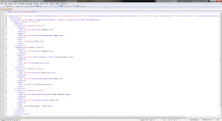
    3. Remove first line in the PTS file using Notepad++ (if necessary). The output should look something like this:

      Here is the Screencast:

      Note: steps 1 to 3 should essentially create a 3 field space delimited XYZ text file with no Intensity, RGB or Normals (sometimes called NEZ by survey people)

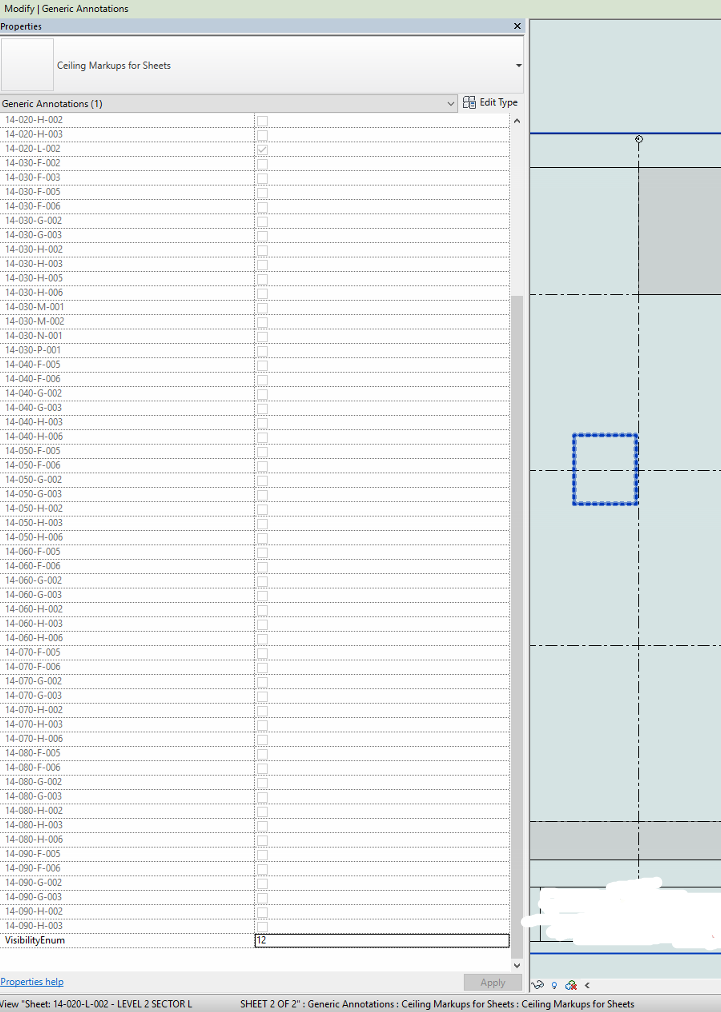
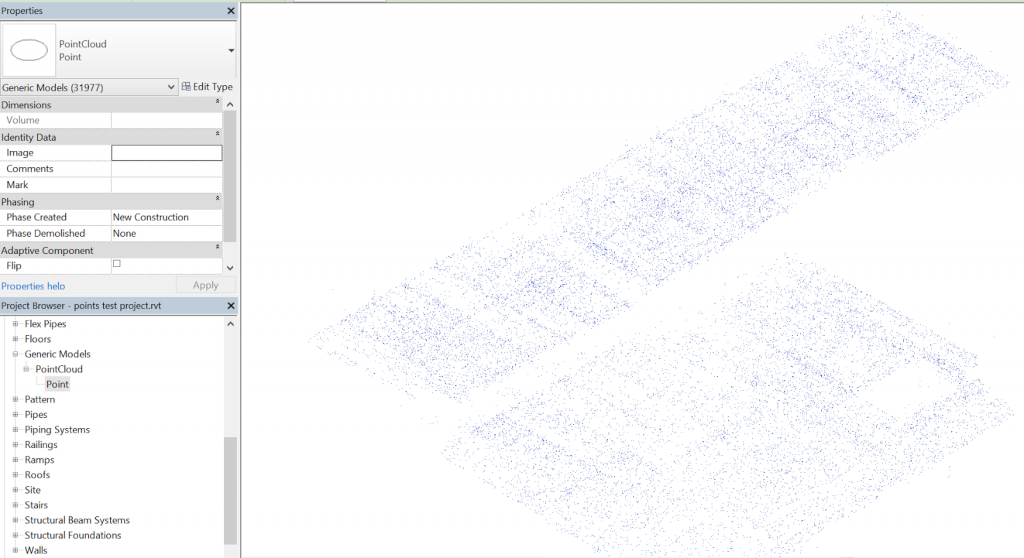
    4. Load some family called PointCloud.rfa with a Type called Point (can be adaptive or not)
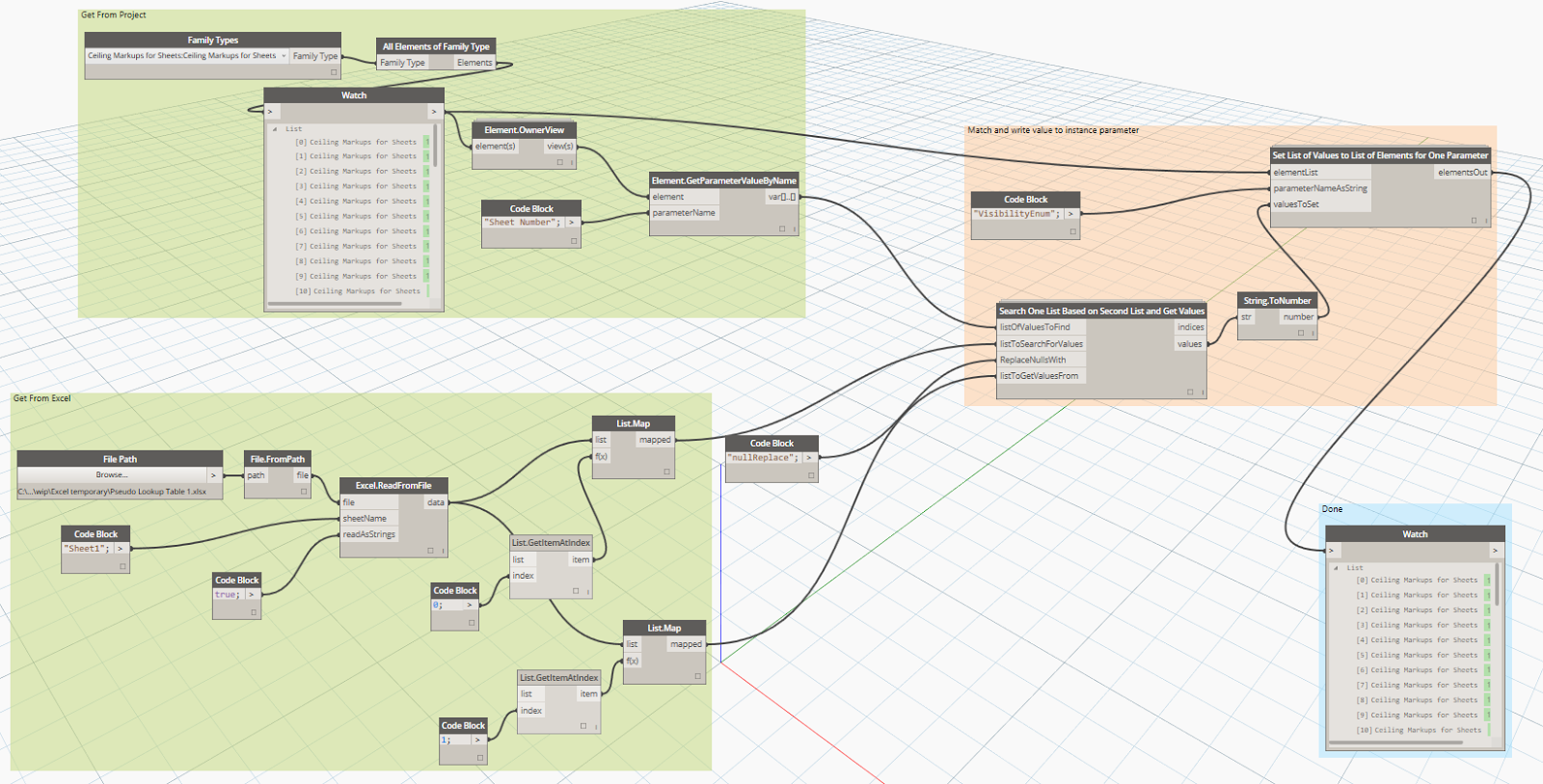
    5. Use a Dynamo definition to place a given family at each location.
      One of my main concerns was scalability.. How many points / instances can Dynamo and Revit handle here? Initially, I used a method where the definition itself threw away a lot of points in a totally arbitrary manner, using a series of DropItemAtIndex nodes. This got me from about 500000 to about 120000 points, and this worked ok. I ended up modifying the node to allow for a number of ‘drops’ (from 0 to 4). Each drop throws away every second point… Finally, as I was getting all the points anyway, I thought it would be nice to have a Topography creation option. The published package can either create families at each point, make a topography, or both.
    6. Once you have generated the geometry you want from the point cloud, then Export to DWG or DXF
    7. Transmit to consultant

    Here is a little readme:
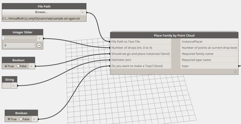
    When you first load the package, you should set up the entry data types as per below:

    If your text file is space-delimited (as mine was), make sure the delimiter string field actual has a Space in it.

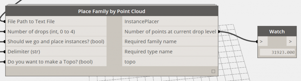
    Also, set the two booleans to False (meaning that no families or topos will be created) for the first Run, and set the drops to 4. The “Number of points” output node will give you an idea of how many points are in play at that particular drop level, like this:

    If you are running on ‘normal’ system hardware, you probably should keep it to around 50000 geometry creation points if possible. On my Surface Pro 3, it could work with the 30000 points no worries, and my workstation could handle 120000 ok. So, once you have a reasonable number in that output box, you can set the go and place instances and / or make a Topo options to True. I think Revit may struggle with huge points on a Topo, but I was able to place the family instances (with a small crosshair or 3D sphere at the origin) and then export to DWG.

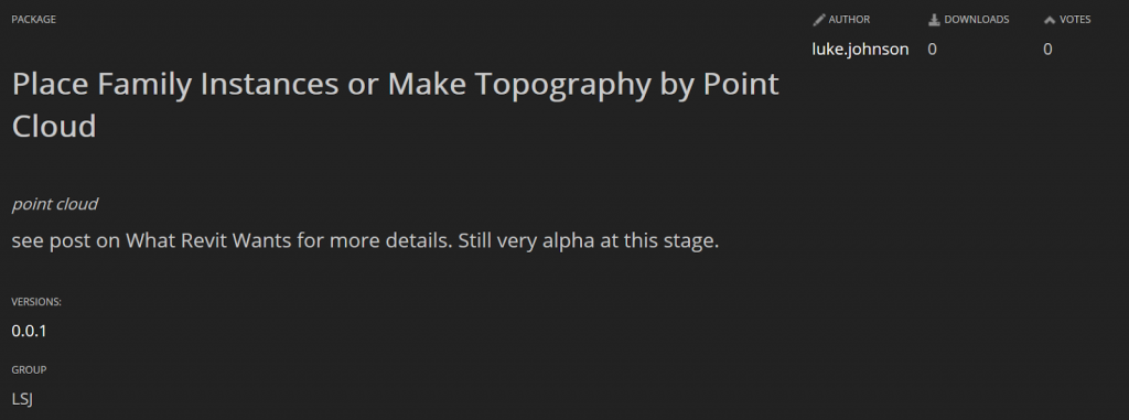
    Keep in mind this is a very arbitrary and lossy method – point clouds were never really meant to be wrestled into geometry like this. However, it may help you in certain situations. The Dynamo node has been published but it is very beta at the moment, so of course the usual disclaimer applies: “use at your own risk”.

    Package is called Place Family Instances or Make Topography by Point Cloud.

    Sample point family for download
     
    A note on coordinates and rounding:
    This tool currently uses project coordinates. A future revision may offer shared coordinate translation. In the meantime, you could use some reference geometry at project base point and run this tool in an new empty, linked file, then move it into place in project. Related discussion:

    Also, it appears that rounding is occurring to 3 decimal places, which is not ideal. Again, this may be fixed in future.

    Endnote:
    I tried lots of other methods, including POINTSIN and IMPORTXYZ lisp routines in AutoCAD, but oftentimes the dataset was too big, or the input data was not what the routine was expecting.
    Some other methods I attempted are below, but they weren’t too successful…
    Also tried:

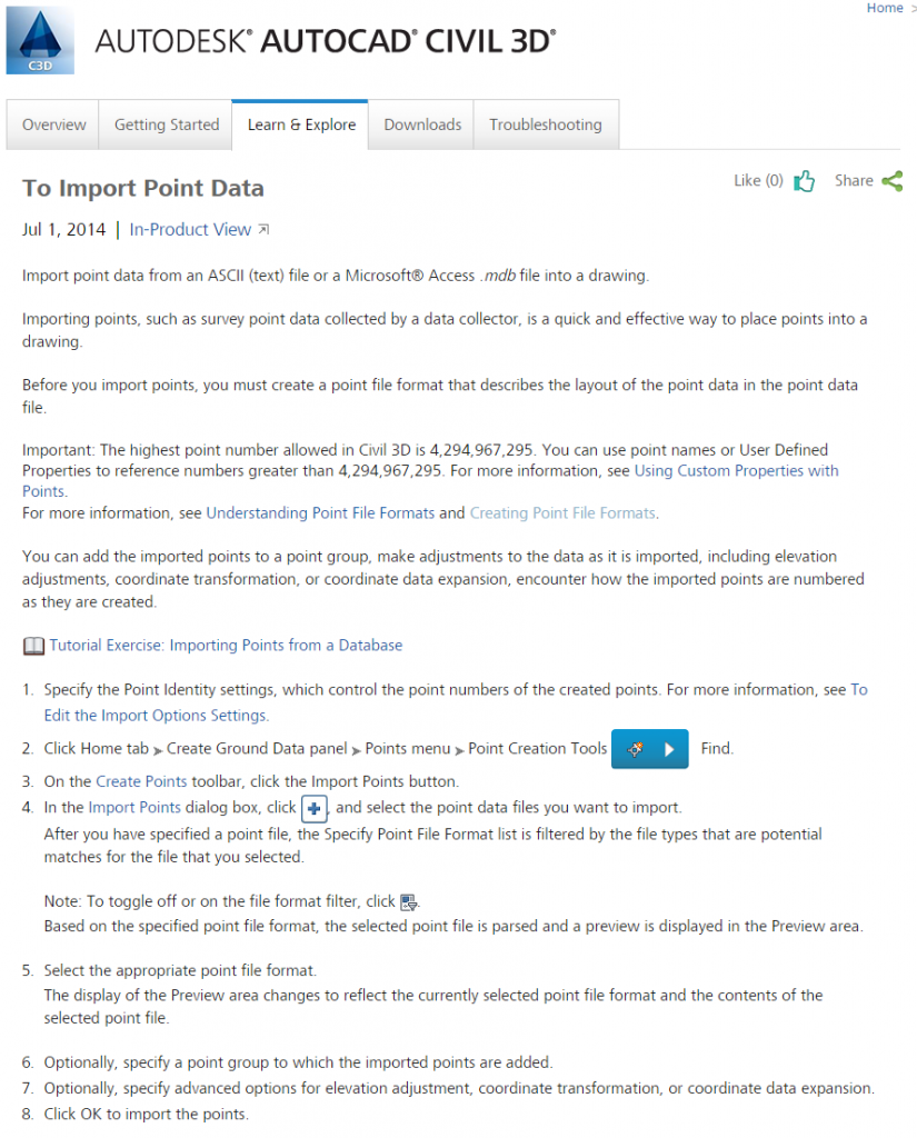
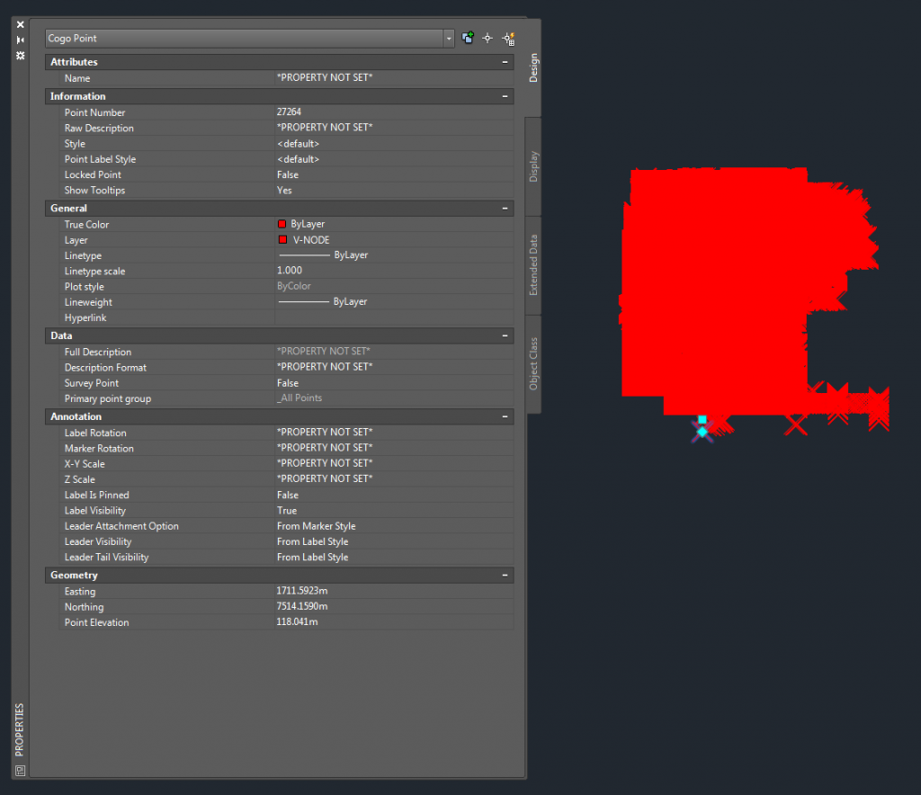
    1. Import points to Civil3D
    2. Convert Civil COGO points to vanilla AutoCAD blocks
    3. Use blocks to generate geometry

    Using Civil3D to Convert Points to LandXML for Import to Tekla Structures
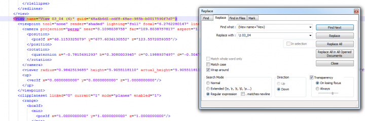
    Another possibility:

    1. Points into Civil3D (as Drawing Objects in a Surface)
    2. Export Surface to LandXML

    Firstly, export the Viewpoints you want to rename to XML.

    Open the XML in Notepad++.  Now we are going to use Search – Replace to append something to the view name in the XML file.  Once we get the Find syntax correct (I used view name=”View), you can just use a backslash 1 in the Replace box to signify the Find result, and then add whatever you like after that.  See the image:

     (make sure you pick the Regular Expression radio button)

    Click Replace All, then save the XML (make sure you just click save, and don’t click Save As).  Now, import it back into your Saved Viewpoints in Navisworks.

     This is what it looks like in Navisworks after re-importing the XML:

    Keep in mind that the import / export process will result in your Hide/Required and Override Material boxes becoming unticked for each imported view.

    This is another good reason that you should be using Appearance Profiler by now… Have you noticed Presenter has now been completely replaced by Autodesk Rendering in Navisworks 2015?

    More on Notepad++ renaming:
    regex – How do you do a Find and Insert in Notepad instead of a replace, while using regular expression? – Stack Overflow

    Daniel Gijsbers uses Notepad++ to do some quick editing and creation of similar Navisworks search sets:


    “Let’s create a couple of searchsets that will find the same parts but on different levels.

    He notes that you should import-export-import to make sure GUIDs are not duplicated.

    Read the whole post:

    Daniel on Autodesk AEC software: Navisworks searchset creation
    Update:
    Copying historical post content here as the original link seems to have died:

    Navisworks searchset creation

    If your into planning with Navisworks you have most likely experience with creating searchsets. If you want to create a planning that build up your model per level over time you end up creating a whole lot of searchsets. Creating searchsets in Navisworks can be a bit of a tedious chore. I like to think I have a much faster solution for it. There is one small catch. Don’t panic at the site of xml code.

    First let’s take this model:

    01-8172334

    The exterior walls this model are compound walls and have been split up in parts. In the picture below I have zoomed in on a window.

    02-7385257

    We want a planning where the different parts appear at different times. Basically we want the concrete first, insulation next and masory last.

    First let’s make one searchset that finds all concrete parts from the compound wall

    03-9671259

    Select an element which you would like to find with a searchset and take a look at the properties. Take a look at the selection tree and see where you have something selected. Make sure it’s not geometry when you are working with revit files. There are much more interesting properties when you set the selection resolution to first or last object.

    I tend to find most interesting properties on the element tab of the property window. For this purpose the property by arrow 2 and 3 are good. I have put a blue arrow #4 at the property for base level. I recommend not using this one because an other one is much more usefull. I do need a property that has a value for base level just not this one. The ID number of the level screws up the searchsets. Instead go to the property tab: Base level. This tab also has a property called name but this value does not have the ID number of the level in it’s name. Later you’ll see why that’s better.

    04-9822103

    At arrow one you see the searchset definition: I have created 4 criteria  (technically you could probably do without criteria number 1)

    1. At arrow two I give the searchset a name. I tend to use the values of the criteria seperated by a # for the name. This should give you a rough idea of what the searchset is for.
    06-8713393

    Now we have our first searchset. Ofcourse you could use the interface, switch some properties of the previous searchset and save the new search. This gets tedious quiet quickly…

    On the sets window there is an export searchsets to xml button.
    Next go to http://notepad-plus-plus.org/download/
    If you don’t have install rights on your machine than you can also put this on a usb drive and run it from there. You’ll have to look around a bit on how to do that but it’s fairly simple.

    Let’s take a look at the xml code:
    Most likely you will be most interested in all the things that are coloured black!
    Also click on the words between < > they will highlight

    Notice the line numbers on the left:
    line 1 to 3 ignore those. leave them in.
    Line 4 is important. Notice the word selectionsetS
    Selectionsets can contain multiple selectionset (no S)
    Line 5 the selectionset stores it’s name from Navisworks here. This line is important
    Line 6 Defines where to search in which models in Navisworks

    07-7850998
    Let’s create a couple of searchsets that will find the same parts but on different levels.
    On line 55 you see that this selectionset ends.
    1. Put your cursor behind  and press enter.
    2. Put your cursors at the first position on line 56
    3. Start dragging a selection from line 56 to line 5
    4. ctrl c
    5. Put your cursor at the first position on line 56
    6. ctrl v as many times as you need
    7. Go to notepath++ menu view collapse level 4 or 3 ( I want the selection sets to look like this image below
    collapsing levels will let you rename the name of the searchsets quickly. You are dependant here on a decent naming scheme in revit….. I assume that there is some structure in your level names that should allow for quick changes
    09-1686064
    Next a find and replace
    10-5207418
    1. go to view
    2. search and replace
    3. put your cursor somewhere in the second searchset. (that’s between line 56 and 89)
    4. let it search for the value you want to replace
    5. click on replace
    After you click on replace it will jump to the next one. Change the replace value and do it again and again and again until your are done. If you would have used the property in Navisworks with the ID number stored you would have been in trouble here. You would have to find and match those.
    1. save as: Part#Basic Wall#plattegrond#Beton – C25/30
    2. save as: Part#Basic Wall#plattegrond#Isolatie
    3. Find and Replace the material names. You should be able to use replace all
    4. Save the file again
    Go to explorer and you should have at least two searchset xml files:
    11-3388948
    1. Go to Navisworks
    2. Delete the existing searchset
    3. Import the searchsets, one at the time… (same button)
    4. Create a folder structure of you liking. I tend to use Revit categories as folder names
    5. Put the searchsets in
    6. Export the searchsets again
    7. delete all searchsets
    8. Import the file you just exported, WHY?
    Why?
    With my methode you get searchsets that have the same guid… First when I started out doing this I would change the guids myself. That’s tedious. Recently I found out that when Navisworks exports searchsets it checks if the guids are the same and if they are it changes them for you. What’s the guid doing here? I have no idea. But’s probably better to have unique guids.
    Have fun. You’ll have tons of usefull searchsets in a little bit of time.

    Many of us were quite disturbed by the 2013 Revit Materials Editor.  Aside from its usability (or lack thereof), it seems to be much slower than the 2012 Materials dialog.  Until Revit 2014 comes around, what can you do to speed up the Materials Editor?

    A recent and highly informative post from Aaron Maller (focused particularly on Revit deployment), gives us a few clues:
    Switch all the mat lists to text style, no rendered preview, open the Mat Editor and place it next to the Mat selector, then close it. 
    Read the whole post here

    Have a look at the images below for some ‘hidden’ options:

    Appears to be no way to adjust the rendered swatch?
    After switching to Appearance aspect, a tiny arrow appears…

    We can now adjust this to speed up the Materials Editor.  The above settings seemed to be the fastest
    (Pool of liquid / Draft Quality)

    We can also completely remove the rendered preview image by dragging the splitter just below it:

    Aaron made similar comments in this post on RFO.

    In my case (Building Design Suite 2013 / Revit OneBox), the currently in use MaterialUIconfig was at
    “C:UsersLukeAppDataRoamingAutodeskRevitAutodesk Revit 2013MaterialUIConfig.xml” 

    Upon opening the MaterialUIConfig.xml, you will notice a few settings like:

    MaterialBrowser inSceneMaterialViewHeight=”502″ navigationPaneWidth=”241″ isInSceneMaterialPreviewEnabled=”0″ isNavigationPaneVisible=”1″

    and

    MaterialEditor SplitterPosition=”0″ OGSRenderQuality=”0″ PreviewRenderQuality=”0″ PreviewRenderType=”2″

    I would like to see some documentation from Autodesk to clarify what all of these actually do, but you can see the settings I am using.  If you use Notepad++, you can also open MaterialUIConfig.xml, make some changes in Revit, and then when you switch back to Notepad++ it will prompt you to reload the xml – you can then easily see what each change you make in the Materials Browser / Editor actually does.