A while back, RevitCat got me thinking about the rules associate with family swapping in Revit.  Here are a couple:

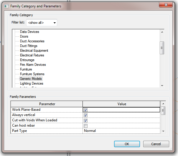
  • You can change the Category of a family (using Edit Family, Load into Project) with a particular name, and all instances of that family will also (obviously) change Category.  Obviously, there are certain restrictions to this process (for instance, you can’t switch to Mass category or from Mass category without some kind of hack).
  • You can swap a family of a certain Category for a totally different family of the same Category using ‘Reload’ in the Project Browser, or ‘Select All Instances’ and then just changing the instances in the Type Selector.

Unless you can reverse engineer this bug, you will have to essentially follow RevitCat’s advice – to change just a single Type of a Family to a different Category, I would probably Edit the Family (from the Project Browser), save/rename it, load it, Select All Instances of the Type you want to switch, change it to the renamed version, and then use the method from the first bullet point above.

In response to:
RevitCat: Changing category of just one type in a Revit family

Another interesting point from his post:
If you plan to change categories of a family, it will appear to wipe out the sub-categories – but actually they are still there, hidden away;  they may show up in the project listed under the old category in Visibility Graphics.

A recent post by Mark Cronin got me thinking… if you can control the arrowhead lineweight for Spot dimensions, can we hack one of these to make a piece of ‘text’ with adjustable arrowhead lineweights?  The answer is yes:

Some people want absolute visual control.  If you are one of those people, check out the example file and see if you can figure out how I did it:
Download

Thanks to:
Leader Arrowheads | betterREVIT

Mark also makes this comment:
So it appears as though the ability to control these parameters is indeed there (and has been for years)! But why can’t they be controlled for text annotation and keynotes, where they would be of most use? 

Personally, I wonder whether Spot dimensions are a ‘newer’ element in terms of Revit version, so perhaps the Factory was able to introduce this visual control here, while still being unable to easily add it to existing elements like text.

EDIT 
If you are wondering how to modify the text, you need to access the annotation symbol family that is referred to in the Spot Coordinate type definition:

After modifying this property, you need to drag or just “touch” the spot coordinate to force it to regenerate.

“a challenge having multiple projects being designed in different versions of Revit.

Four years ago, the data transferred from these links was flawed or incomplete.  Software lockups were common.  With the advancement of the software, communication between Revit and analytical programs has improved but issues still remain.  Four years later, the transfer is still not seamless.

Early discussions regarding clash detection expectations may lead the design team to model elements differently, for instance, just modeling the bond beams in bearing walls to avoid sifting through hundreds of non-critical clashes.

via
BIM: Four Years Later | Ryan Biggs

EDIT via Autodesk Forum

Revit 2014 was just released and an updated version of Andersen’s Window Studio is being tested right now.  Release date is expected in 7 – 10 days, but a pre-release version has been made available for current Revit 2014 users.  This is a 64 bit version of Window Studio 12.1 that has been recompiled using the Revit 2014 API.  Please report any issues you might run into (it is still undergoing testing).  I’ll remove this link when an official version is offered on andersenwindows.com..

Pre release of Window Studio 13.0 for Revit 2014

There are many new features exp>ected in the 13.1 release scheduled for late summer.  One of those features will be the inclusion of exterior trim as designed in Window Studio.  For the intervening months, the following advice might help anyone trying to create their own trim and group it with an Andersen Window.  Hopefully, this workaround will only be needed for a short time.

Since I last posted my last comment about trim, I was sent a generic trim .rfa file I’ve been using.  I was able to place the trim family on my host wall and change the parameters to “almost” match the native Andersen trim.  The model I was sent does not have any cornice,  drip cap, or brick mould so those features would have to be added using the family editor.  I wish I knew the original creator of this trim file so I could give him/her credit, but I’m afraid I did not obtain that info.

Here’s the file.  I took the RO measurements of the Andersen window to set the height and width parameters for this generic trim.  One limitation is that this works for single units only (without editing).  The authentic Andersen trim will render horizontals and verticals for an entire design with no editing needed.  Space between mulled units will either show a 3.5 or 4.5 board or the connecting strip for frame-to-frame joins.

Window Trim RFA File

Christopher Oace
Andersen CAD Support 

Go here to register and download:
http://www.comehometoandersen.com/servlet/Satellite/IQ/Page/awBrochureRequest/ContentServer

Direct link to 64 bit version:
Download

Active / current forum thread:
http://forums.autodesk.com/t5/Autodesk-Revit-Architecture/Andersen-Window-Studio/td-p/3499264

I had a Structural Framing member (a portal frame) and I wanted to demolish only the overhanging part of it.  Using methods like Cut By Face would not have any proper respect for Phasing, so I thought “I’ll use an in-place Structural Framing void”.  Guess what?  In-place families can not cut a Structural Framing family.  What now?  Read on below the bars…

EDIT
Great tip in the comments from Michael Clothier – just use Parts!  Turns out I am guilty of not using current Revit functionality…

You can use a Generic Model Component with a Void, and set the Cut with Voids When Loaded property to Yes:

Here is one I prepared earlier, for you to download and use:
SuperVoid Family download

Ok, once you have loaded and placed this family, you can resize it to suit and then use Cut Geometry to slice up your Structural Framing:

But guess what?  It STILL does not respect Phasing!  Revit will think that the Structural Framing is ‘cut forever’.  Workaround – copy the original Structural Framing element, Paste Aligned to same place and then use another SuperVoid to chop that one with the opposite geometry.  Now that you have two bits, you can set Phasing to suit.  This is starting to get messy though, and it may all be better if you just had two different Structural Framing families to make this work…

You will also notice that the SuperVoid family has model lines locked to the edges.  Use the instance parameter Edge Lines vis to turn these off.

Heads-up from the Autodesk Forums:

Create a Generic Model . Just model a void extrusion e.g. Enable Cut with Void.
Place the void family and cut it with your framing family…..
Model in Place won’t work.

Regards Jordi

via
Void component cutting beams – Autodesk Discussion Groups

Can be downloaded at this link:
https://docs.google.com/file/d/0B1dGdRkpk2beQjBNMDdxbXMxaTA/edit?usp=sharing

Received via Mark Kelly, Cadgroup Australia Pty Ltd.  It is dated October 2012.  Thanks Mark!

Apparently, this file will be available for general download soon.  In the meantime, Natspec made the following disclaimers:

·       The keynote file is provided on an “as is” and “as available” basis without warranty of any kind.

·       NATSPEC makes no warranty that the file will meet your requirements or expectations.

·       Use of the file is at your own discretion and risk. NATSPEC takes no responsibility for any problems that might arise from its use.

·       NATSPEC does not provide support services for any modelling software. Please contact your vendor for assistance.

You may also be interested in my previous posts:
Australian Revit Keynotes and NATSPEC

NATSPEC BIM Portal

Doing an interesting roundtrip today:

  1. Export Revit floor plan to DWG – basic walls / doors / floors only
  2. Add floor finishes / landscape / people / vehicles in Impression
  3. Save PDF, open in Photoshop
  4. Add extra Entourage (furniture etc) and text in Photoshop
  5. Save for Web and re-import into Revit.  Scale to match floor plan from step 1.

It may sound like a pain, but its working quite nicely…

Having some problems with a Railing that will not show up in a Detail View unless balusters are added to it!  Video:

I’m almost certain this is related to this previously posted bug:
Extents of Revit 2013 Railings bug – when no balusters exist in definition

More on Revit 2013 railings:
Automatic and Manual Railing Support locations in Revit 2013

Revit 2013 railings – almost 7 months old, but have you used them?

An interesting post by Daniel Burrus on LinkedIn has been doing the social media rounds.  Some quotes:
Every profession has both a science and an art. The science can be taught, and people can be equally good at the science of any profession. The key to differentiate yourself in your profession is to develop the art side, not just the science side.

The same is true with any profession, whether you are in sales, IT, customer service, or even medicine. After all, if healing was only a science, it wouldn’t matter who your doctor was. But you and I both know it does matter who your doctor is, and it’s not because of the science; it’s because of the art. It’s about what the individual brings to their medical practice—their uniqueness, their problem-solving ability, their diagnostic capabilities, and their way of solving problems in real time when they’re working on you.

Obviously, this principle holds true for Revit.  Just knowing how the tools work and where to find them in the Ribbon does not mean that you know the Art of Revit.  The Art of Revit involves:

  • Understanding What Revit Wants.
  • Being able to analyze 5 different ways of doing things, and being able to choose the best one.
  • Solving problems by thinking through the process, not just by asking someone.
  • Finding completely new ways to solve old problems.
  • Knowing how to break the rules, and knowing when the rules should be broken.

Of course, the Art of Revit also involves being able to do cool things like Marcello and David

Heads-up via this tweet from Aaron:

Led me to this page:
There Is a Science and an Art to Every Profession | LinkedIn

Install the Google Drive desktop utility and the Skydrive desktop utility.  After syncing both of these utilities / folders, you will have an offline version of both sets of documents in folders like:

Then, use FreeFileSync to sync folders locally.  For example, I made a subfolder on my Skydrive called Google_Drive and synced all of my Drive documents to that Skydrive folder.  You would have to do something similar in the opposite direction too.

Once the desktop utilities have re-synced, you now have access to all of your docs from each cloud.

Note:  Skydrive docs can’t open .gdoc yet.

You may have guessed that I have started using Skydrive due to my recent acquisition of a Windows Phone 8 device, a Nokia Lumia 820…

More info:
Google Drive Help