
From RevitKB at original post:
https://plus.google.com/109857765963579790247/posts/cf53adrVDjP
Along similar lines, check out:
Set up a NICE 3D View Template … for quick Cameras
What Revit Wants

From RevitKB at original post:
https://plus.google.com/109857765963579790247/posts/cf53adrVDjP
Along similar lines, check out:
Set up a NICE 3D View Template … for quick Cameras
Here’s one that has been sitting in my draft posts for a while…
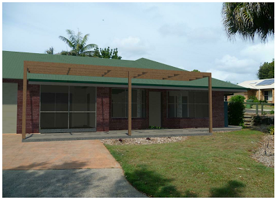
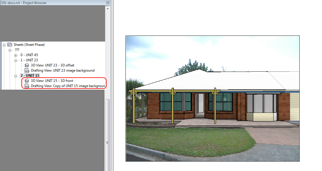
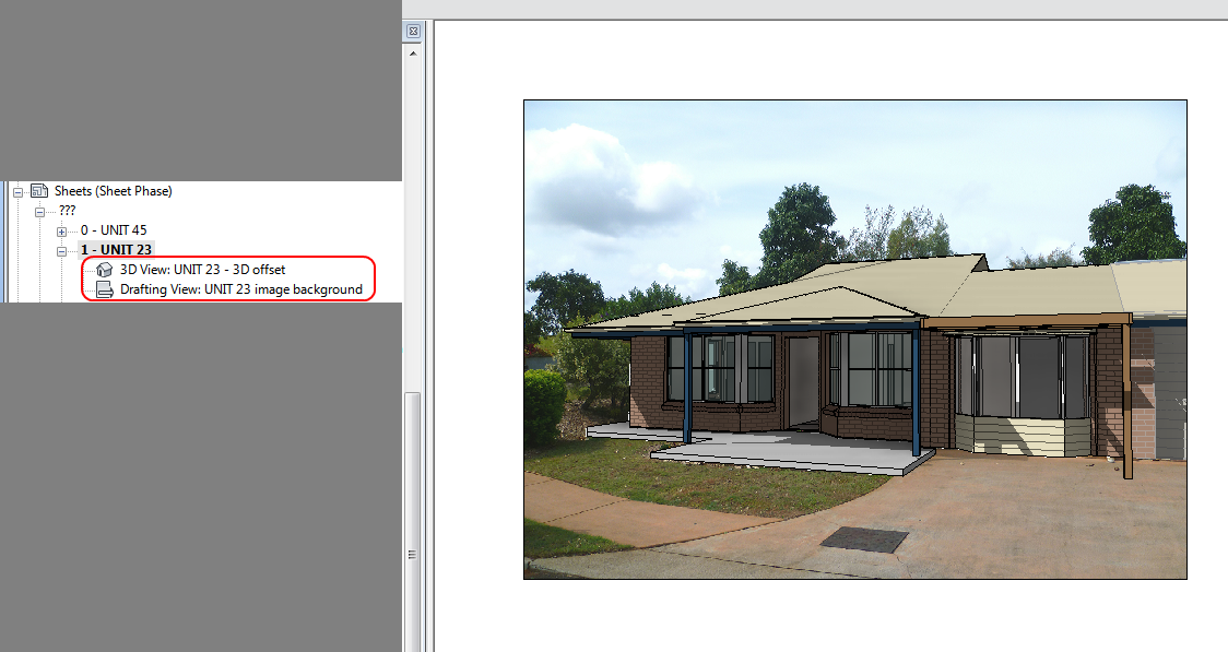
Basically, its an example of what you can do by overlaying views on Sheets. In this case, I have used a Drafting View with an imported Image, as a background to a 3D Camera View. As this was an alteration job on an existing dwelling, I was able to essentially ‘line up’ my Revit Camera with the physical camera location. After a bit of tweaking, I had basically matched the Camera to the Photo.
Then, its simply a matter of putting the 3D View on top of the Drafting View on a Sheet.
Now you have a photo background to a live 3D view – you don’t have to re-render to see the changes to your building. You can use various visual styles like Shaded or even Realistic. I hope some of you find this technique useful!

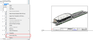
You may want to do a very aggressive cleanup of your Revit file, getting rid of all Views while retaining all 3D elements as proper Revit elements. You can use the ‘Save to New File’ function to do this. (Note: when I say aggressive, I mean it – use at your own risk, and be sure to verify the contents of the output file). Thanks to the revitogbim blog for this tip.
This is the trick: when you right-click a 3D view, the Save to New File option is grayed out, but when you put it on a sheet – its back!
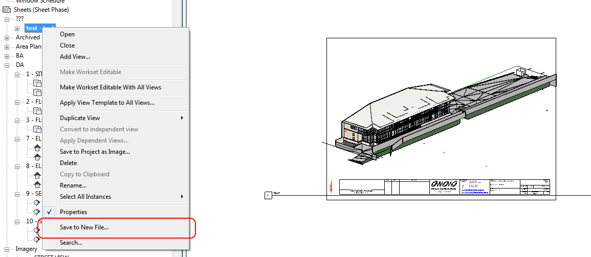
Here’s how to do it:
Views in the resultant file:
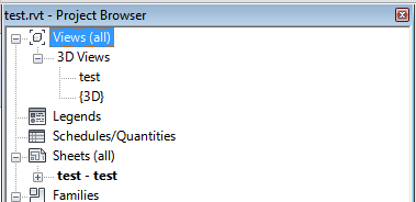
(the following lists are not exhaustive)
Things that are removed:
Things that are retained:
To make things look right, you will probably need to Transfer Project Standards for things like:
For my test case, I also turned off all Annotation Categories in the original 3D view, and I scaled it so it would fit the sheet.
This workflow and the basic steps were from:
Translated version
of
http://revitogbim.blogspot.com.au/2012/10/model-export.html

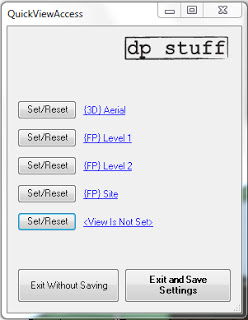
a Revit plug-in that you can assign 5 of your most often used views.
It is super simple in operation. When you run it for a very first time none of the views are set and you have to set those that you want to be able to access by clicking on the “Set/Reset” button
…
download page to get the installation files or download them directly from here.
via
DP stuff: QuickViewAccess for Revit 2012, Access Your Most Often Used Views
I requested a 2013 version from Dima Chiriacov in the comments – he replied that one will be available ‘very soon’…
EDIT via MLD in the comments:
In a 3D view;
1 Ensure Section box covers all elements by,Unchecking then rechecking ‘Section Box’
2 Select some objects and the section box
3 Temporary isolate elements
4 Uncheck then recheck ‘Section Box’ again
5 Reset Temporary Hide/Isolate
Another way – is the COINS Auto-Section Box add-in available on Autodesk Exchange. Install the add-in, restart Revit, select a few objects then click the button. It will create a section box around those objects in the selected 3D view – very easy!
Download at:
Autodesk Exchange Apps

A third way – is through a nice tip posted by Trey at Wikihelp. Here are the basic steps:
I have spent hours trying to figure out how to take actual camera locations from 123D (Photofly) and get them into Revit as ‘real’ cameras (3D views). I thought it would be cool to be able to use a real-life camera location in Revit, because then you would already have the existing scenery as a background image (because 123D Catch would have used it in processing the model). This was partly in response to this comment.
Its easy to export an FBX from 123D Catch, and open that in 3ds Max – you get cameras, yay. You can use FBXIMPORT in AutoCAD and you get the named views (cameras), yay.
However, I have not been able to find an equivalent process for Revit. At this point, I have to admit defeat.
My big idea was to convert the FBX into IFC with view information in the schema, and then open that IFC in Revit. Sadly, I kept coming up against problems. AutoCAD Architecture can import FBX and then export IFC, but the 3D views do not seem to come through.
One possible workaround would to compose your presentation in Showcase – you can export from Revit to Showcase, and you can also export an FBX from 123D and bring that into Showcase too. But I want a purely Revit way.
If you have any thoughts on how to make this happen, PLEASE comment 🙂
Here is a list of links and notes that you may find useful. There are some really cool resources on IFC available now – read on below:
NOTES on FBX and IFC
Autodesk sign in is required on 123D Catch to actually activate the Export feature to allow exporting of FBX.
Explanation of the export formats available from 123D (formerly Photofly):
| Menu Command | Format | Contents |
|---|---|---|
| .3dp | The 3D photo scene contains cameras, reference points, 3D mesh, reference lines, and distance measures. This is the native format for Project Photofly. | |
| .dwg | The drawing contains reference points and reference lines. | |
| .fbx | The Autodesk FBX asset exchange file contains the 3D cameras, the photo textured 3D mesh, reference points, reference lines, and reference labels. | |
| .rzi | The ImageModeler file is a subset of the 3dp file based on what was selected at the time the photo scene was exported. | |
| .obj | The OBJect file contains the photo textured 3D mesh. | |
| .ipm | The Inventor Publisher Mobile file contains the photo textured 3D mesh and can be viewed with the free Inventor Publisher Viewer available in the Apple iTunes App Store. | |
| .las | The binary LASer file contains the 3D point cloud that was automatically extracted from the pixels of the source photographs. The LAS file format version is 1.2. |
Camera Support – 3ds max and FBX
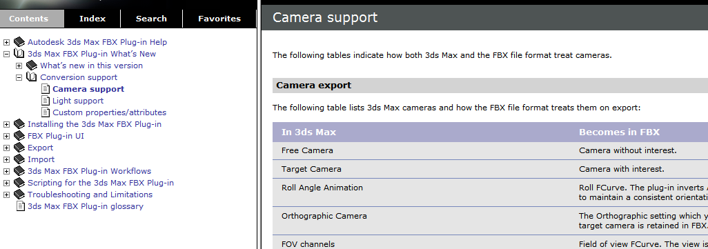
http://download.autodesk.com/us/fbx/20112/3dsmax/files/WS1a9193826455f5ff6026605b1181237e94650be.htm
AutoCAD Architecture IFC export information
http://exchange.autodesk.com/autocadarchitecture/enu/online-help/browse#WS73099cc142f4875510b13df10ec0b2c48a-7a62.htm
3D views can be export FROM Revit TO AutoCAD Architecture
http://wikihelp.autodesk.com/Revit/enu/2013/Help/00001-Revit_He0/1468-Document1468/2171-Print_Ex2171/2172-Export2172/2245-Structur2245/2251-Exportin2251
List of IFC softwares, tools and viewers
http://www.buildingsmart-tech.org/implementation/get-started/ifc-toolboxes/ifc-toolboxes-summary
IFC schema information for views (plans, sections, 3d views etc)
Context
http://www.buildingsmart-tech.org/ifc/IFC2x4/rc2/html/schema/ifcrepresentationresource/lexical/ifcgeometricrepresentationcontext.htm
Subcontext
http://www.buildingsmart-tech.org/ifc/IFC2x4/rc2/html/schema/ifcrepresentationresource/lexical/ifcgeometricrepresentationsubcontext.htm
DDSViewer – can view DWG and IFC
http://www.dds-cad.net/132x2x0.xhtml
To get a free version of the DDS Viewer, visit the ftp server and download DDSViewer.exe
IfcWebViewer – online web viewer for IFC using WebGL
http://code.google.com/p/ifcwebserver/wiki/IfcWebViewer
Exporting cameras as .3ds files using Flame
http://wikihelp.autodesk.com/Flame_Premium/enu/2013/Help/01_Flame_Premium_–_Flame/2037-3D_Compo2037/2267-Action%3A_2267/2274-Importin2274/2276-3ds_Max_2276
Vectorworks and 3ds
http://www.scribd.com/doc/34074946/128/Importing-and-Exporting-in-3ds-Format
Showcase can import views from FBX files
http://download.autodesk.com/global/docs/showcase2013/en_us/index.html?url=files/Help_ImportSettings.htm,topicNumber=d30e2896
IFC to OBJ:
IfcOpenShell
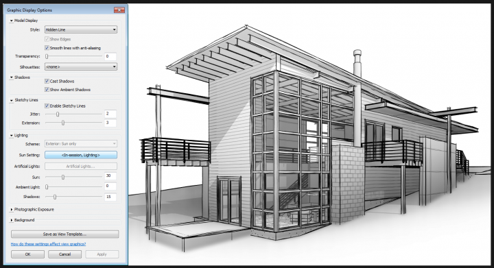
When making a standard perspective Camera View, Revit 2013 allows you to effectively preset View properties, so that all new Camera views look nice. These settings are from the BIM Technologist:
Then, save the View Template settings and go into the Type Properties of 3D View, and set the View Template applied to new views appropriately.
via
How to do it:
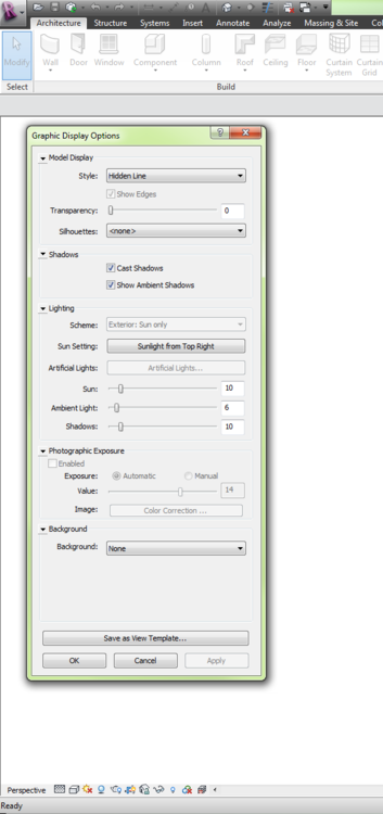
You can even do this in a Hidden Line or Wireframe view.
Shadows do not need to be turned on.
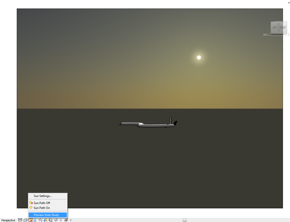
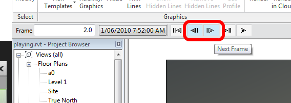
If you want to quickly move the sun around WITHOUT having to use the graphic sun path:
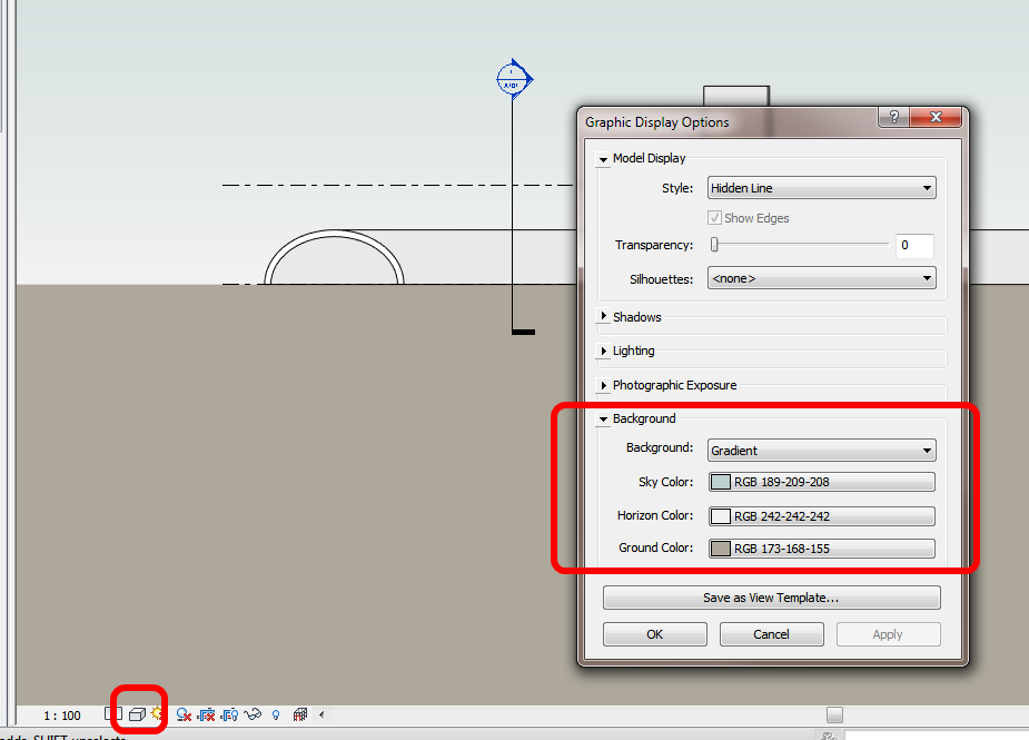
You can now add a background to Section and Elevations views using the Hidden Line visual style.
Ever wanted to constrain your orbit to only the X or Y axis in Revit? Here is one way to do it:
via
Disable Mouse Movement on One Axis – Tech Salsa