In previous versions of Revit, a common workaround to generate some ‘depth’ in elevation views was to use transparent mass planes.  This created an effect like this:

Here is what was actually happening behind the scenes:

However, something has been changed in Revit 2012.  This no longer works properly.  In fact, you CAN open up a 2011 file that has the effect in 2012 – and the effect will remain.  However, if you purge the file, it simply disappears!  See example video of this ‘Disappearing Act’ and file download link below:

Example file download link

The only way I have been able to retrospectively ‘add’ the effect to 2012 is:

  1. Open a 2011 file that has the effect.
  2. Rename any relevant masses or materials in the 2012 file so that you can cleanly ‘paste’ the 2011 mass.
  3. Copy one of the mass planes from the 2011 file and paste it into the 2012 file.
  4. This ‘might’ work for you…
  5. You can’t EVER purge this file in 2012, or the effect will break.

If you want to follow the discussions on this issue, here are some forum links:
http://forums.augi.com/showpost.php?p=1130343&postcount=41

http://revitforum.org/showthread.php/1958-2012-Kills-the-Elevation-Mass-Transparency-Workaround

Let me know if you have any comments or workarounds for this.

Ever wanted to fillet between 3D edges in Revit?  Some of the limitations of 3D modelling in Revit were discussed at RTCAUS, so I thought I would try a little ‘tech demo’ of sorts…

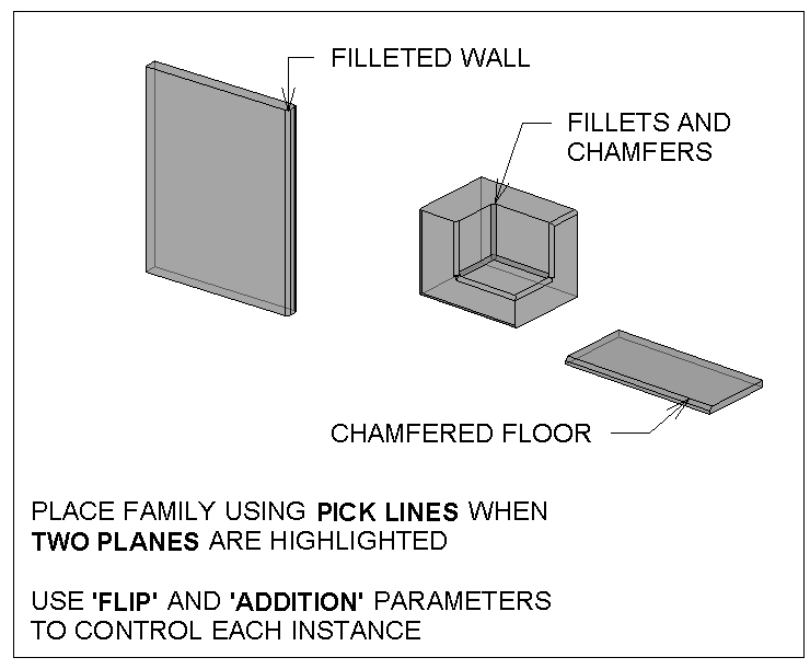
Revit 2012 gives us an opportunity to do some nice things with in-project voids.  Below, you see corners of a Wall, Floor, and Generic Model being filleted and chamfered (chamfer is the word we use in Australia for a ‘diagonal’ or triangular fillet).

Basically, I have created two line-based Generic Model families.  These are called:
Chamfer line based void and solid family D.rfa (the triangular form)

Fillet line based void and solid family D.rfa (the arc fillet form)

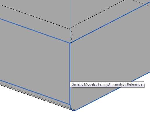
I then load these into a project.  When placing these families in 3D, if  you place them when two perpendicular planes are highlighted at the same time, you get some nice control.  If you do this, Revit places the item ‘on’ one plane, and ‘aligned’ to the other plane.

These families can do two things to the edge – cut a void, or add a fillet.  You use the ‘Flip’ Yes / No parameter to get it in the right spot, and the ‘addition’ Yes / No parameter to choose if you want the item to show the ‘fillet’ solid part.

Feel free to download the example and have a play with it.  Sure, there are some limitations to this method, but some of you may find it useful.

Do you have a more elegant solution to this?  Feel free to comment…

Heaps of PDF presentations are available at this page. Here are some direct links:

Revit Architecture Forum (17th May 2011) Event Summary and Presentations 31.8MB

Revit MEP Forum (18th May 2011) Event Summary and Presentations 29.9MB”

Revit Structure Forum (12th May 2011) Event Summary and Presentations 19.6MB

Design Visualisation Forum (11th May 2011) Event Summary and Presentations 5.4MB

AutoCAD Civil 3D Forum (13th May 2011) Event Summary and Presentations 16.1MB

From
Spring User Groups in London:

Microsoft has released a beta version of recovery tool that can help the users to start their infected PC when all other anti-virus solutions fail…

Download Microsoft Standalone System Sweeper Beta version (1.0.856.0):

Microsoft Standalone System Sweeper Beta (32 bit): mssstool32.exe
Microsoft Standalone System Sweeper Beta (64 bit): mssstool64.exe

via

Download Microsoft Standalone System Sweeper for Offline Scan and Start Unbootable PC