
So close! 🙂
AI Empowered Project Management
So close! 🙂
Check them both out at:
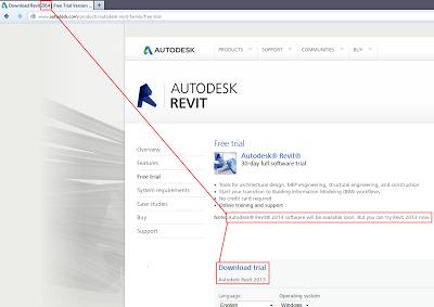
Revit | Building Design and Construction | Autodesk
Of the items currently revealed, these are the BIG ones (in my opinion):
From Daniel Gijsbers blog:
“if you try to open a revit workshared file (central file) with LT it right away makes a copy of the file with LT added to it’s name.
But what is even more surprising it leaves the central file intact. With that I mean I saved the central file in Revit LT and next I open the same file in it’s bigger brother. Big Revit says right away: Would you like to create a new local? In other words, you are trying to open a central file. Revit LT doesn’t throw away the worksets!
When you have opened the file take a look at the worksharing display
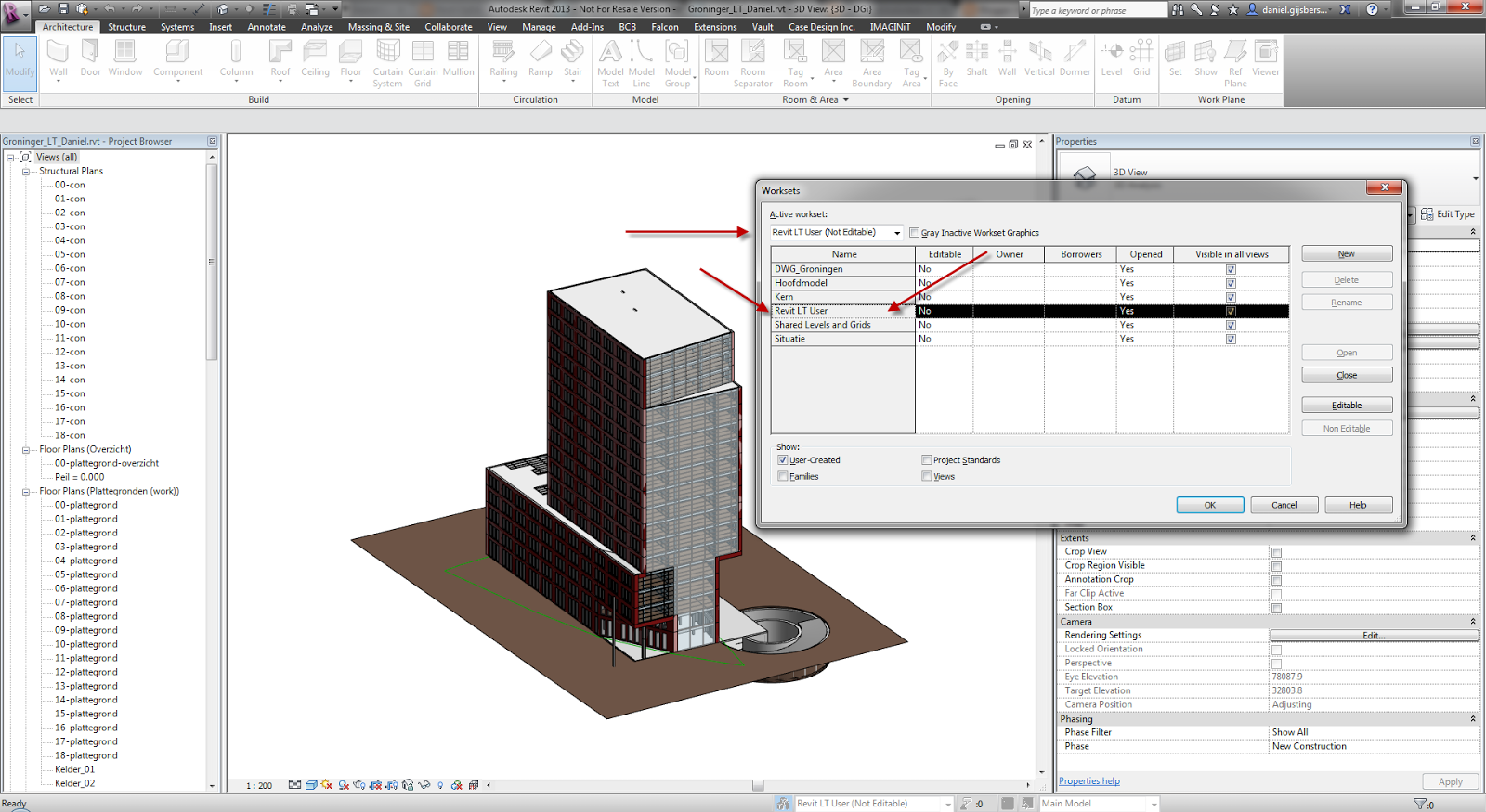
Revit LT has created it’s own workset… called Revit LT user”
Read more about the implications of this:
Daniel on Autodesk AEC software: Revit files and Revit LT
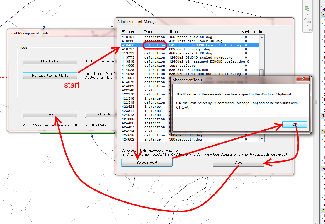
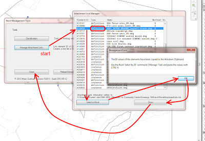
Sometimes you will have some junk imported DWG definitions residing in your project. These may be present due to the long history of the project, perhaps using Transfer Project Standards – View Templates, or just poor RVT model management.
How can you get rid of them?
There are various paid tools that will let you do it, but if you already have access to the Whitefeet Tools, you can use them to easily delete any import definitions (they don’t have to be DWGs) that you no longer want in the model.
Here’s how to do it:
Now, when you go to your VG – Imported Categories list, that particular Import will no longer be present.
Congratulations, your model just got cleaner!
Nice tip + addin coming from Trevor Taylor via Jeremy Tammik – it shows how to rename Interior Elevation views by the Room that they reside in.
Download:
Here is a complete sample project including a test model in case you’d like to check it out yourself.
Many thanks to Trevor for this useful tool, his research, implementation, and generous sharing.
Read more / via:
The Building Coder: Rename View by Matching Elevation Tag with Room
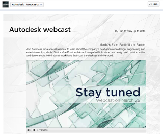
EDIT: Live stream embedded below
Check it out:

Link:
Autodesk Webcast
Heads-up:
March 26, Autodesk to announce…??? facebook.com/autodesk click on webcasts to find out more!
— Scott D Davis (@scottddavis) March 20, 2013
You have to register before you can download… included are families for Heat Pumps, Condensing Units, Controllers and more.

Heads-up:
https://twitter.com/specifinder/status/314313741426626560
Today is the 21 March 2014. Last year, the NDA was lifted on Revit 2013 around 27 March. There have been whispers of Revit 2014 features getting released on the LARUG blog, over at Revit OpEd and a few things happening on Twitter. LARUG even has a little countdown widget to – guess which date – March 27, 2013.
So, I think I’ll just get ahead of the game a bit here…
To find out all the new features of Revit 2014, head over to http://autodesk-revit.blogspot.com.au/ (insert sub page here: [http://autodesk-revit.blogspot.com.au/2013/03/whats-new-in-revit-2014.html] on or around March 27 🙂
Just for reference, this was Dave Light’s post from last year, posted 27 March (it still gets reposted nearly every week to someone’s blog, somewhere in the world):
Revit: What’s new in Autodesk Revit 2013?
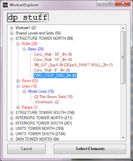
A new Revit addin from Dima over at dp stuff can do that – it looks like this:

The tool is pretty straightforward, so I will try to describe just in a few words how it works (the demo video in the beginning of the post shows it as well).
– assuming you already installed the WorksetExplorer, run the tool from dpStuff Utils in Add-on tab.
– the dialog box will open and in the “tree” your elements will be sorted by workset, then by category, then by family, then by type.
– every “branch” will have a name and the amount of elements on it in parentheses.
– once you see something that shouldn’t be on a particular workset then you can select the branch and click “Select Elements” button – that will add elements that belong to this branch to selection.
– now you can send them to the workset they are supposed to be on.
– repeat until all worksets are in good shape.
You can download the WorksetExplorer add-on from our download page or directly from this link.
via
dp Stuff: WorksetExplorer Revit Add In – What’s On Your Worksets?
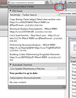
Click on the little satellite dish, then InfoCenter settings:
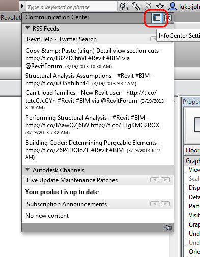
Go to RSS Feeds and click Add, then copy and paste the following string:
http://search.twitter.com/search.atom?q=RevitHelp
Done!
While you are at it, why not add What Revit Wants:
http://feeds.feedburner.com/WhatRevitWants
Notes:
Twitter RSS that doesn’t work in Communications Centre:
https://api.twitter.com/1/statuses/user_timeline.rss?screen_name=RevitHelp
Read more:
Is there any way to display my tweets via an rss url? | Twitter Developers:

