I had one of those slap-your-head moments when this finally came to me … use Coins Auto Section Box!
Step by step:
- Close Revit
- Install Coins Auto Section Box
- Open Revit
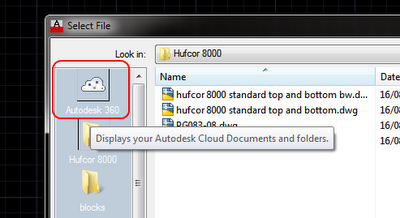
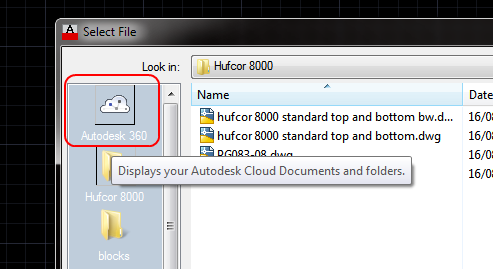
- Open a project
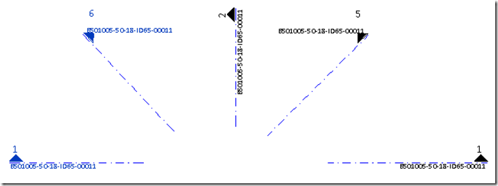
- Draw a Scope Box
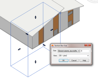
- Go to a 3D view where you want to match the Scope Box
- Select the Scope Box
- Go to Add-Ins > Auto Section Box
- Set Element extents, plus buffer: to 0
- Hit OK!
The 3D view now has a Section Box that matches the selected Scope Box.
I previously tried to implement some sample code from The Building Code, but couldn’t make it work (see below the lines). I’m sure this is due to my less-than-optimal API skills…

How to compile code SLN for Revit (using Building Coder as example:)
- Download the ZIP
- Unzip it
- Double click SetSectionBox.sln and open it in Visual C# Express (or use SharpDevelop, see below)
- Click on the Reference Paths side-tab
- Using the … add your Program FilesAutodeskRevit 2013Program directory
it is looking for RevitAPI.dll and RevitAPIUI.dll - Right-click on the SetSectionBox node and press build
- Find the setsectionboxsrcSetSectionBoxSetSectionBoxbinRelease folder, and copy the SetSectionBox.dll
- Paste it into %AppData%AutodeskRevitAddins2013
- If it isn’t already there, paste SetSectionBox.addin into the same folder.
Revit 2013 ships with the open source IDE SharpDevelop.
If you want to use SharpDevelop:
“yourdrive:Program FilesAutodeskRevit 2013ProgramSDAbinSharpDevelop.exe”
Just drag and drop the solution file into the SharpDevelop window.
Running the command, I get a couple of different errors. One is:
Revit encountered a Autodesk.Revit.Exceptions.ArgumentException: Box is
empty
Parameter name: box
at Autodesk. Revit.DB.View3D.set_SectionBox(BoundingBoxXYZ section Box)
at SetSectionBox.Command.Execute(ExternaiCommandData
commandData, String& message, ElementSet elements)
at apiManagedExecuteCommand(AString* assemblyName, AString*
className, AString* vendorDescription, MFCApp* pMFCApp, DBView*
pDBView, AString* message,
Set< Elementldstd::less tnallc< Elementld> > • ids,
Map tnallc > * data, AString*
exceptionName, AString* exceptionMessage)
Here is SetSectionBox.zip containing the complete source code, Visual Studio solution, and add-in manifest of this command.
via
The Building Coder: Set View Section Box to Match Scope Box