Fellow Expert Elite Karam Baki has posted an interesting workaround for ‘converting’ between differently hosted Revit families. The term converting isn’t quite accurate, really we are just ‘nesting’ the hosted family into another family until we get to the hosting type that we want. There are times when this will help you, but other times you may go through all of this and then decide “hey, I should have just rebuilt that family properly from the start because Revit keeps crashing now” 🙂

Here’s the basic steps:

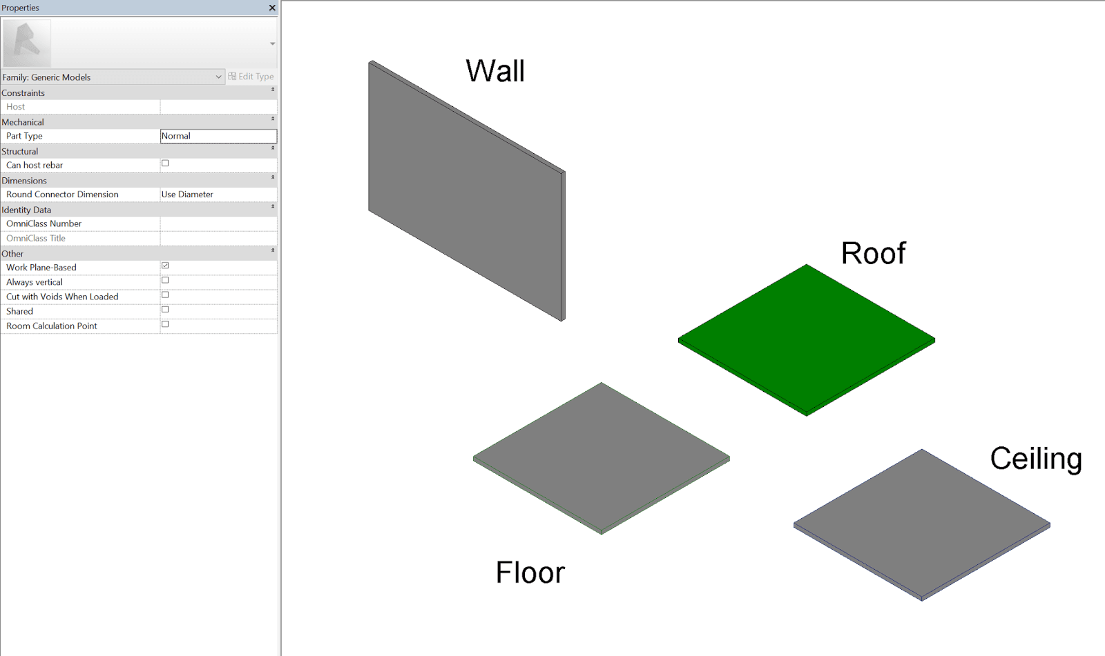
  1. Use a special middleman family with System category elements living inside it… (Karam has provided one on Google Drive)
  2. Load your hosted family into that special family and host it onto the object that it wants (Wall, Floor, Ceiling, Roof)
  3. Work with parameters as needed, link them through etc if needed.
  4. Save As ‘unhosted’ version of your family
  5. If needed, nest this again into a new, clean family based on whatever category / hosting you want
  6. Get origins, void cuts, openings working and link through the necessary parameters…

As a general comment, I’d say you should test thoroughly in your own environment, because this whole workflow is not really ‘#GoodRevit’ in the sense that we are breaking certain rules to get the results we want.

Along similar lines, you may remember the Copy / Monitor hack that allows converting between some different types of hosting:
Convert Family from Wall to Face based

Back in 2011 I posted about some related workflows, including the necessary steps to get System family elements in a normal Component family:
Save an In-Place Family as an RFA for use in another project
Create a Component Family with Category set to Walls (or other system family category)

You can also make unhosted Doors and Windows from scratch, like this:
Making unhosted components like unhosted Doors and Windows

Original post by Karam Baki:
Revit Tip: Save Time Converting Revit Families – Autodesk Community

You can watch his video here:

I have posted about SysExporter a few times before, but here is a little reminder… You can use SysExporter to grab text from almost any dialog box in any program in Windows. Let’s say you have a list of missing materials in a Revit Render dialog box. You can use SysExporter to grab that list so you can find the material images and rectify the problem.

Here’s how:

  1. Render a scene
  2. When the missing material dialog pops up, start SysExporter
  3. Find the dialog in the list (you can use the target to drag and drop onto the Rendering dialog)
  4. Once you find the list of names, you can copy / paste them, or export to a file
  5. Find the missing materials and point your Revit install at them using the Render Appearance Paths in Revit Options.

You can get it here.

This site usually focuses on intermediate to advanced workflows and topics, but here I just wanted to mention a couple of getting started resources that you may find useful. There is a new and comprehensive video playlist on the BIMscape channel, and I have embedded it here:

And don’t forget about the Autodesk Design Academy. For example, the link below will take you to a Revit and Architecture Fundamentals online training course. All for free, of course.
https://academy.autodesk.com/curriculum/fundamentals-architecture

Revit Wants you to have a unique Detail Number for each Viewport placed on a Sheet. This makes total sense, and allows you to trace from a Referencing View, through a View Tag (telling you which Sheet and Detail Number that View is on), and back again… The Viewport knows which Detail Number it is, and which Sheet is referenced from.

Ok, that is What Revit Wants. And in fact, it doesn’t allow you to have duplicate Detail Numbers,

detail%2Bnumber.png

… because that would be madness, right? Well, in some Architectural firms, they may have drafting standards which indicate something like this:

  1. We will reference Interior Elevations from our General Arrangement Floor Plan
  2. The View Tags will have letters a, b, c, d and so on for each Room
  3. These Interior Elevation views will be placed together on Sheets
  4. We will append the Room number to the Detail Number so that we can figure out which Elevation a is which…
  5. Meaning that there will be multiple Detail Numbers that could be the same on each Interior Elevation Sheet

I’m not going to speak to the validity (?) of this logic, but lets just say sometimes drafting standards from past ways of doing things don’t mix so well with Revit. How do we work around this problem?

I’m not so proud of this, but it is one of those hacks that just seems to work…

  1. Create the Viewport Title Tag with a Shared Parameter for the View Room Number, and the Detail number in one label together
  2. Use a special invisible character to make the Revit program think the Detail Number is different, when it appears exactly the same to human eyes… as I said this is bad Revit

How do you do step 2? Just copy one of these characters from your Character Map and paste it after the Detail Number that Revit doesn’t want you to have. So you type ‘a’, then press Ctrl+V to paste the special character in to the Detail Number parameter:

zero%2Bwidth%2Bspace.png

This is the Unicode character U+200B: Zero Width Space.

Oh, and have you ever wanted to get rid of that annoying question mark in a Revit Tag because there is no value? Just put in one of these Zero Width Space characters and it will go away 😉

Ok, bring on the Comments 🙂


In Revit, each Link is bound to both a Type and an Instance. So you can have one Link ‘Type’ – relating to a single RVT file that is linked into the project. But it can be placed multiple times in the project, thus having multiple instances. In workshared projects, the Type and the Instance can belong to different Worksets.

Did you know you can use Linked Views to display two identical copies of the same linked model in different ways?

To add control, you should create 3 worksets – 1 for the Type, and 1 for each Instance, as shown below:

Then, set up two different Linked Views in that linked model. In this particular case, I want to use a model converted from ArchiCAD to a single Revit file. But I want to be able to separately load and display the Site objects, and the Building objects. So I have an Link Instance for each, and linked views for each. The whole rig can be seen in the image below.

Using the worksets, I can separately Load / Unload each Instance (closing a Workset unloads any Link instances on that Workset from memory). And using the Linked Views and Overrides for the Instance, I can display each instance as I like. I can also load both instances and show both in a ‘combined’ view.

Final note: Link Instances can be located in different positions in the Host model, and they can have different Shared Coordinates. Using the methods above, you have a lot of flexibility to be able to use a single linked Revit model in many different ways…

A federated Revit model is a model containing many Revit links, and they can be quite slow to work with. There are a few steps you can take to speed things up, and one of them is creating a set of fast view types and a related view template.

Here’s how:

  1. Make a View Template called “No Model” and untick all the Model categories in that Template
  2. Make a set of View Types called “Fast Plan“, “Fast Section” and so on
  3. Set the View Template for those Types to the “No Model” template you created

Now, when cutting sections or making new floor plans using these ‘fast’ view types, the view will generate quickly without any model elements. Then, you can decide if you want to switch view templates / types to something more useful for coordination or documentation.

Ok, two unrelated issues here, but both are along the lines of “weird stuff that happens in Revit that can be fixed but doesn’t always make sense”. If you use Revit long enough, you will certainly come across issues like this…

Firstly, certain Electrical penetration families were not tagging for height when using Spot elevations. These elements were in a model, which was linked into another model. The fix? Super weird one. Try turning on Lighting Fixtures in your View (in the host model). Then, those spot elevations worked… Even though the penetration family was a Generic Model with Nested Mechanical Equipment inside a link file. I’m thinking this one was either an upgrade error, or perhaps the families had some earlier history as a Lighting Fixture?!?

Secondly, I came across a Structural Consultant Design Model in Revit 2015 that doesn’t want to upgrade to Revit 2016. This is due to some corruption inside various families. Here are a few things to try… along with the ultimate solution.

1) Try opening the model in the newer version of Revit with Detach and Audit ticked, and choose Specify from the Worksets dialog dropdown. If the Opening Worksets dialog appears, Close all the Worksets and press OK. Then, Detach and preserve worksets. You should see the Model Upgrade progress dialog.

This fails with the following error:
The file cannot be opened. There are too many elements missing in it. Please contact Autodesk Support.

2) Next steps are more detailed and resulted in a successful upgrade:

1. Open in 2015, with Audit and Detach, no Worksets open
2. Save As
3. Open in 2016, with Audit and Detach, no Worksets open
a. Delete families when prompted (as you can see, it is one problem Rebar family)
b.

c. Ok to mass errors:
d.

e. Click to resolve Join errors
f. 

4. Save As
5. Setup starting view…

And here are some model tidy-up steps that I did, just #GoodRevit with some Dynamo:
6. Make these worksets:
a. Hide-CADs
b. Hide-Topo
c. Link-Control
7. Move DWGs to workset by:
a. Getting Ids in Dynamo
b.

c. Group
d. Change Workset
e. Set workset invisible
8. Move Topo to workset and set invisible

9. Acquire Coordinates from Control Model
a. Copy / paste control model from current ST file to this upgraded one
b. Link neutral coordinate file
i. Acquire
c. Then acquire from BMGR control file
d. Save

Finally, sharing with team:
10. Save to Box
11. Open in Fed
12. Glue

Interesting question raised by Rene Pellicer Garcia on LinkedIn recently:
I found that I just couldn’t make real Revit curved mullions (of the right category, schedulable, measurable, etc). Best I could do was a geometry that looks very mullion-like, but can’t schedule it, measure it or quantify it…

It is one of those situations where there are many ways to accomplish the same task, and those methods could include:

  • Traditional family modelling
  • Adaptive components
  • Dynamo
  • Non-typical modelling (railings, structural framing etc)

I decided to give it a go with the Adaptive Component method. Here’s how I attacked the problem:

  1. Created an adaptive profile family
  2. Nested that into a 3 point Arc Mullion Adaptive family, and hosted it on the arc reference line
  3. In the Arc Mullion Adaptive, made the main mullion form from the profile and the arc
  4. Created a rig of Reference Lines to host the Arc Length Dimension
  5. Used some hosted points on the Arc as intersected references for the Arc Length Dimension
  6. Made a shared, instance, reporting parameter on the Arc Length Dimension

    https://wrw.is/wp-content/uploads/2016/10/family2Brig.png

  7. Loaded that family into the Mass form family
  8. Placed it with 3 point click placement
  9. Selected the Instance and used Repeat command to make it into a Repeater
  10. Did similar for horizontal mullions
  11. Noticed some places where it ‘broke’ – mostly where the Arc Length Dimension flips inside out or goes straight — considered making a ‘straight’ version of the family for these locations?
  12. Made a schedule, filtered by Type Mark, showing these Arc Lengths

    https://wrw.is/wp-content/uploads/2016/10/project.png

  13. For the purpose of Identification, made a quick Dynamo Script to auto-populate the Mark parameter:

https://wrw.is/wp-content/uploads/2016/10/dynamo2Bmark.png

I’m sure my solution is not perfect, but it is one way of attacking the problem. It could be finetuned to be more robust and provide a nice modelling output.

You can download my modified sample file here, containing the adaptive components.

LinkedIn discussion:
Creating schedulable curved mullions in Revit