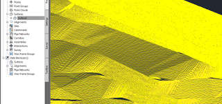
Will turn this:
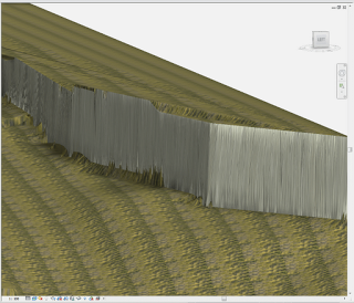
Into this:
What Revit Wants + Black Grid AI
AI Empowered Project Management
You receive a DWG file from a surveyor, and you need to get it into Revit. You go through all the usual cleanup steps. You have purged, scaled, done a write-block, audited. You link the DWG into Revit, create the topo – and it looks like rubbish.
If your survey data has some severe gradient, perhaps relating to a steep retaining wall on the site, you may find that Revit does not model it ‘smoothly’. Here is an example
The problem is likely related to Revit’s triangulation method for topo surfaces. You get weird flat surfaces where things should look much smoother and more organic.
Here is a quick workflow that I have used to add some realism to a survey DWG without sacrificing accuracy (note – this method uses AutoCAD Civil3D, you can download a trial):
 |
| Lots of contours here – thanks Civil3D |
The result? Something with a much more ‘organic’ appearance:
 |
| Better Revit surface (Realistic View, Edges off, Subregion applied) |
Obviously, this method has a couple of caveats:
Also, using my Quadro FX580, if there were too many points, my computer would basically just hard-crash to a BSOD – save often! I ended up switching to software emulation (turning off Hardware Acceleration in Revit).
One of the greatest things about Revit, and BIM in general, is that we usually design ‘in context’ – that is, with as much site information as we can get our hands on…
Vasari has that handy little option to import a Google Earth image into your model – well now, Revit has an add-in that does a bit more, including:
It is called:
CADtoEarth | Autodesk Revit | Autodesk Exchange Apps
Here is a quick guide on importing topography from Google Earth:
Heads-up:
http://revitaddons.blogspot.com.au/2012/08/cadtoearth.html
From their website:
(embedded JWPlayer)
In Revit, you can’t use the linework tool on the physical edge of a Toposurface. Worse still, the edge has no distinct category of its own.
The only viable workaround that lets you consistently hide the edge of a Toposurface is to change its Object Style color to white. You can still set you Primary and Secondary contours to show in black or whatever color you use.
This method creates its own problems – like if you draw a grey filled region over the edge of the Toposurface, the ‘white’ line may show through and print. In any case, feel free to ask Autodesk for some better visibility control over Toposurface elements.
While you are at it, why not ask for Toposurfaces to comprehend phasing properly?
Tip via:
AUGI – View Single Post – Linework tool w/ Topography
There are at least two ways to work around the fact that a Plan Region will not affect the viewing of Topography elements. From the AUGI forums (2007):
Alex Page
What about having a ‘cut-plane’ of the view above the topography and doing a plan region around your house? (ie: reverse the logic)
Steve_Stafford
You could try creating a view of the toposurface from a higher vantage point that doesn’t include showing the building. Then overlay this view with the view of the building (overlay on a sheet that is) at the level you want without the toposurface. This way the two views give you the whole but permit the two different cut planes you really need. If you set the toposurface view to wireframe it should give you the look you want, guessing what that really is, though.
via
Plan regions have no effect on Topography?? [Archive] – AUGI
Simply:
Video example below:
BIM blog.ca describes how to go through the following work method (step by step):
Now you can (kinda) do your site survey using your camera 🙂
via
BIM blog.ca: From Photos to Point Clouds and Topo in Revit
You know when you have two pads meeting at a common edge, and then Revit for some reason shows this tiny sliver of created topography between them?
Try this:
This tip worked for me – I hope it helps you. I’m pretty sure that there are still situations where things still just won’t quite work…but for the time being, Revit Wants you to set adjacent Pad levels at the same value.
Tip via this thread
Pads Pads Pads…oh and there’s a problem – AUGI
Navigate to where you want to be and get as close as you can.
Start to create a placemark by clicking the pushpin icon.
In the placemark’s dialog box, click the “View” tab.
Change the number in the “Range” field to 500m.
Then believe it or not, click “Cancel” and you will see yourself zoom out to 500 meters altitude.
Google Earth’s placemark dialog box has the range setting in meters regardless of whether you have feet or meters set as your default in Tools –> Options. If you wanted exactly 500 feet, you would need to convert to meters and enter the meters value in the Range field.
via Appletom post at
How to Set Altitude in Google Earth
With regard to the datum of measurement for altitude, this statement from the above thread may be helpful:
Summary – when terrain is on, Google Earth’s eye altitude represents ASL (Above Sea Level). When terrain is off, Google Earth’s eye altitude represents AGL (Above Ground Level).
You can turn terrain on and off in Tools – Options.
There are actually 5 different ways that Google Earth measures altitude:
Clamped to ground
Clamped to sea floor
Relative to ground
Relative to sea floor
Absolute
For more information on these, check out the post at this link.
Sometimes you may have trouble using a DWG that contains ‘points’ to create a Revit topography.
There are two main ways around this.
METHOD 1
Here is a LISP routine to export points in a DWG to CSV file:
http://www.revitcity.com/forum_files/69930_RegCoorPointsCsv.lsp
These points can then be imported when making a Revit topography by selecting ‘Specify Points File’ on the Ribbon.
via
RevitCity.com | Topo point does not import?
METHOD 2
Alternatively, you can Replace the points with some other object that Revit will make use of more easily (for instance, a block with some very short lines). To do this, use the ‘RP’ LISP routine from the following post:
Re: Replace point with block/object – Autodesk Discussion Groups