Not a great position to be in (having point clouds with different coordinate systems and no known common point), but here is some code that may help: andymiller/FeatureBasedAlignment · GitHub
From GibHub: The goal is to accurately register two point clouds created from different image spectrums (e.g. visual to infrared), in different coordinate systems of different scales. … Current approach is: – Take two point clouds – Estimate normals for each point – Find FPFH Features for each point – Find likely correspondences between two models (based on FPFH) – Use top features to estimate scale, – Run RANSAC to estimate transformation, and eliminate correspondences – Use remaining correspondences to run ICP for finer alignment
I find it interesting that we can receive a point cloud (laser scan) of a project, which essentially describes the geometry and colour of the whole 3D space, and yet have to re-model everything in Revit elements to make it actually useful in a BIM / FM context.
It reminds me of the early days of document OCR – you could scan a document, but there was no easy way to infer the intelligence (text) of the document. Happily, OCR software improved, and I hope that geometry-from-point-cloud automation will also improve. Bring on the automatic, one-click “Make a Building from my Point Cloud” solution. In the meantime…
This post is about my experience working with point clouds and Revit 2013 on a recent project. I explored various different workflows and add-ins. I will add to this post over time to make it as useful as possible.
On the project in question, we received the following from the surveyor:
Leica TruView data set
RCS point cloud
PTX point cloud
A note on file formats: PTX files keep scanner information (including roto-translation in the head, each point keeps all information XYZIRGB, allowing surface normals to be calculated). Interestingly “Many scan packages including Polyworks, Rapidform, and MeshLab read the PTX format and offer meshing operations that will allow you to create a polygonal mesh from a PTX”. PTS files are simply the point locations and RGB values, each point forming a new row of data in the file. (more here)
We did not receive:
3D geometry or Revit elements of any kind
We knew that:
the surveyor was using a Cyclone 8.0 database (Leica)
There are a number of different workflows available:
native Revit tools (in my case, using Revit 2013)
Scan to BIM add-in by Imaginit / Rand (around $3000 for Standalone license)
Leica Cloudworx for Revit (around $4000)
Visualizing in Navisworks and modelling in Revit
Revit 2012 and the Point Cloud Feature Extraction labs add-in (if you can find it anywhere)
using Point Clouds in the Revit Family environment
Note 1: I initially had problems using a combination of Revit 2013, Scan to BIM and Leica Cloudworx. For example, Wall Region Grow would report “No points found in this area?” However, if you zoom in and click exactly on a visible point from the Cloudworx point cloud, Scan to BIM should be able to pick it up. A representative of Imaginit / Rand reports that Clients often do use both tools together.
Note 2: Note 1 is apparently a known issue. Workaround with 2014 and Recap is to bring the raw format scan into Recap, export it out as a .pcg file. Create a new project inside of recap and bring in that pcg file and save that off as a rcp… that error msg should no longer appear. (Thanks Cheyne Bird, IMAGINiT Australia)
Initial thoughts: Scan to BIM seems to be the better tool for feature extraction and geometry creation, while Leica Cloudworx puts you in direct contact with the original point cloud data – not decimated by Revit.
General Tips:
Revit will consume big amounts of memory when working with large point clouds
Rule of thumb – indexing a 27 gb PTX will result in a 7gb PCG and will take about 7 hours for a mid-range PC.
Indexing 2 x 27 gb PTX using Recap version 1.0 and basically default settings about 6 hours 8gb for new PCG
Working with 2 of these 7gb PCG files in Revit 2013 on XP64 with Scan to BIM will consume about 11gb of RAM easily. You may have to periodically close and re-open Revit, depending on your system specs.
Working on the same point files using Cloudworx will consume about 2gb of RAM, depending on your view settings.
If you are using Revit 2013 and you want to restrict Revit from highlighting (pre selecting) a point cloud, which can be annoying, just place it in a Design Option. It seems that Scan to BIM can still interact with a Point Cloud in a primary option of an option set.
Did you know that Point Clouds when imported to Revit have a Phase Created and a Phase Demolished parameter? Revit respects this when it comes to Phase Filters and Graphic Overrides – keep this in mind if you can’t ‘find’ a point cloud in your project.
You will be working in 3D a lot, and making lots of 3D views cropped to section boxes. I recommend that you set keyboard shortcuts for: Orient to a Plane, and Set Current View as HomeUsing these shortcuts, you can quickly reorient yourself and use the Viewcube properly.
The above workplane shortcuts work well after using the “Set Workplane” tools in the various add-ins. After triggering Orient to a Plan, just click OK. When Revit says -not associated-, it means ‘use the current workplane’. You should also set and use a keyboard shortcut for the Show Workplane button on the Home tab.
When making a new 3D view, the quickest way is to select an existing Section Box and copy it using Revit copy (not Ctrl C) and drop it close to new desired location. It will appear in Project Browser with same name as previous 3D view, but with any digit on the end of the view advanced by 1. This is actually better than using Duplicate View, which adds this silly “Copy of” to the front of the new view name. Note: This new Section Box will also remain selected, so you can adjust the crop before switching to the newly created view
You may wish to turn off “Snap to Remote Objects” in your Revit snaps, these can get in the way when working with Scan to BIM, and Point Clouds generally
To facilitate setting of a Workplane based on already modelled geometry, I made a simple 3 point adaptive component with a surface formed by these 3 points. You can use Set Workplane to pick this triangulated plane and work from there.
Scan to BIM:
I recommend you watch this video to start:
You can also access an archive of webcasts by filling out this form. Workflow (walls):
Crop 3D view with Section Box as much as possible
Use Wall Region Grow tool (3 point click on face)
Adjust wall edge extents
Rinse and repeat
Carving – A quick way to reduce the extent of the wall is to use the Split Tool – rather than trying to find the edge, just Split the wall horizontally or vertically or both, and delete the bit you don’t need.
Sloping / Slanted Walls – You can either use the Wall by Face option on the Wall Region Grow tool, or create an inplace wall out of extrusions by using the Set Workplane tool. The latter is preferred if you want to modify the resulting wall in any way.
Optionally – use the “Work on Wall” button, Select Wall, and use the resulting section to edit wall profile, add windows etc.
Workflow (topography): The topo creation tools in Scan to BIM work great. You essentially get to pick points, choose decimation, and then you get a topo. Easy, right? Well, then you have to clean it up.
Workflow (columns): I suggest you get rid of all column types in the project, and just keep one Round and one Rectangular OOTB column family loaded. If you use Structural Columns, you can schedule them…
Crop 3D view with Section Box as much as possible
Pick appropriate column tool (Round or Rect)
Make a crossing window over column points
Pick correct column type family or load a new one
Click Create Column
Note – you may have a bit more joy if you switch the 3D view to “Top” before selection the column crossing window
For angled columns, you can use the Slanted – End Point Driven option in the Properties Palette. In fact, if you want to tweak column height while in a 3D view, switch to Slanted – End Point Driven, adjust using the end points, and then switch back to vertical…
Workflow (floors):
Crop 3D view with Section Box as much as possible
Determine an approximate height for the floor
Sketch the floor outline, using the height from 2
Select the Slab, and then start the Scan to BIM Adjust Slab tool
Select points
Tip – in a 3D view when using the Adjust Slab tool, you may have a better experience if you switch to Wireframe first. This stops model elements from occluding the Analysis Result that shows you the slab deviation.
Personally, I find the use of Floors to be a bit more frustrating than that of Topos. It would be nice to have a Floor tool that works essentially the same as the Topo one – select a bunch of points, decimate them heavily, and use them as the top surface of a Floor element.
Workflow (Curtain Walls and Glazing): This is a simple two point click. Use “Work on Wall” to make a perpendicular wall section of the hosting wall. Then click one corner and then the other of the glazed area. Adjust mullions according to point cloud.
How to get it: To get Scan to BIM, use these links:
To use Cloudworx add-in for Revit, you must have Cyclone installed
I had a GUID conflict for the Revit add-in when installing Cloudworx, I posted the resolution here
I also had a license error. I had to open Cyclone itself and switch it to VIEWER mode. I ended up receiving a trial license.dat, and put this in the appropriate folder.
We received a folder containing the Cyclone databases. The key file is an IMP file. In Cyclone:
Configure – Databases
Add…
Select the IMP file
The surveyors database will now be accessible to you
To use this data in Revit: Add-ins, Import ModelSpace View. Then drill down in the Cyclone database until you find the appropriate view. I found one based on a known coordinate system and it was a ‘unified’ view.
You can import multiple point cloud sources.
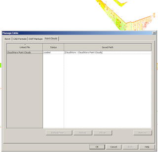
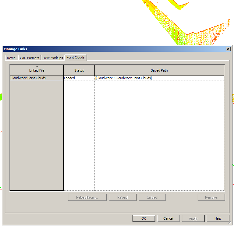
Cloudworx plugin strips out existing point clouds from the project and replaces it with a database link, that looks like this:
I immediately noticed that navigation (using Revit 2013) was much faster with Cloudworx than with the native PCG files.
As you zoom in and out, Cloudworx will ‘throw away’ or add points to keep the view relevant to your context (as well as maintaining graphic performance). Use the Rendering options on the Cloudworx ribbon to set your desired view (such as True Colour).
When you save the Revit project containing the Cloudworx DB link, you will be prompted to save a .cwprj file. Make sure you do this. After closing and re-opening Revit, the Cloudworx data will be gone. You use the Open option from the Cloudworx add-in to recover your previous work (view links, view settings etc).
Workflow: Once you have imported the Cloudworx database, the essential workflow seems to be:
Clip a view to the elements you want to model
Use the Workplane command from the add-in (this make a new workplane from surrounding points and sets it current)
Make a new in-place family, with geometry (typically extrusions) based on this workplane
Rinse and repeat
What’s it for: Cloudworx doesn’t have anywhere near the sophisticated geometry creation tools included in Scan to BIM. However, it does provide a facility for clipping point clouds, visualizing them, saving view states and setting workplanes. In terms of exploring the Point Cloud, it is actually the superior tool. You just can’t make anything “Revit” from it.
Introductions by Andrea Fournier, Instruction by Michael Harvey and David Langley
Description:
This class is an in-depth look at the CloudWorx for Revit software. Follow along with the instructors with the supplied database to practice each of the concepts. Items that the class covers are slicing, clipping, limit box, drafting walls, drafting floors, drafting pipes, and many more.
You need to register before accessing the training…
Using Points In Families In videos below, the following workflow is described:
Clip points in Recap
Save as PTS file. Optionally, compress to LAS using this workflow.
Use a LISP tool like PointsIn or PTSIN to import Point Cloud to a AutoCAD DWG file. Optionally, place a block element at each point to allow easy snapping in Revit.
Import the DWG to a Revit Family of your choice
Do your modelling, and save and load your Family into the Project. Recommended – delete the source DWG and purge the Family to decrease overhead.
Videos: Playlist of LTC3D videos embedded below. Of particular interest:
video showing Edgewise workflow (automated pipe creation)
video showing the clipping of points in Recap, then import to AutoCAD using PTSIN, then Import to family environment. This allows creation of component families using point data (alternative method would be to make an in-place family in the project environment and then save to RFA).
Using Cloudworx Plugin: 9.The next stage is to bring in the point cloud from a Model Space. From the Add-Ins tabs choose Import MS View, fill in the correct settings for the Connection String and Coordinate Systems. Note that Cloudworx is automatically defaulting to the internal units of Revit (Feet) but that it is correctly applying a scale factor.via Point Clouds in Revit – BIM Toolbox
Creating Geometry (snapping): Controlling visibility: Control the visibility of the point cloud on the Imported Categories tab of the Visibility/Graphics Overrides dialog, as well as on a per-element basis. You can switch the visibility of the point cloud on or off, but you cannot change graphical settings, such as Lines, Patterns, or Halftone.
Creating geometry: A snapping feature simplifies model creation based on point cloud data. Geometry creation or modification tools in Revit (such as wall, line, grid, rotate, move, etc.) can snap to implicit planar surfaces that are dynamically detected in the point cloud. Revit only detects planes that are perpendicular to the current work plane (in plan, section, or 3D) and only in a small vicinity of the cursor. However, after the work plane is detected, it is used as a global reference until the view is zoomed in or out. via the Revit 2013 wiki at Using Point Cloud Files in a Project – WikiHelp
Scan to BIM workflows PDF: This is a pre Revit 2012 workflow and uses AutoCAD as middle man quite heavily… it also recommends Scan to BIM: GORUG Presentation April 5th – Andre Carvalho
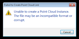
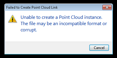
It goes without saying that you can’t interrupt a point indexing process in Revit – you will probably end up with a corrupt point file, as per:
@oatfedgoat beginging to think it was because I fell asleep and shut my laptop by accident at 62% now !! #latenightBIM — Mark Taylor (@mstjohntaylor) August 23, 2013
PS. Why do I have this feeling that this might be my most visited post this year?
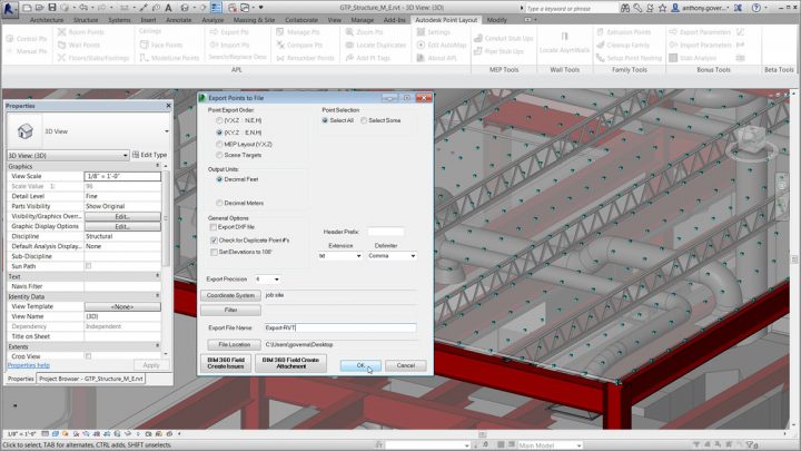
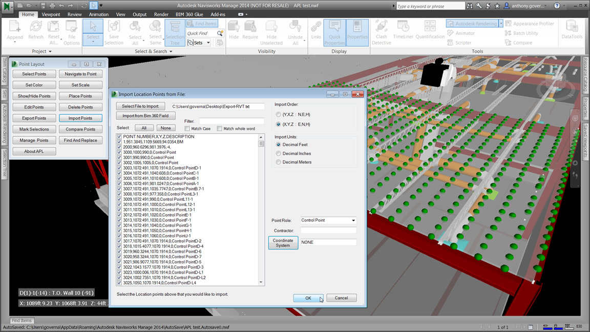
Interesting – this kind of turns the point cloud technology upside down… It goes something like this:
Revit model
to points
to site survey hardware (set out the building)
build it
then laser scan the as constructed
compare points of the as built model for quality control
The part I’m trying to get my head around is this – these aren’t really point clouds, but rather, they are setout points of Revit BIM 3D elements for construction use. Perhaps the word ‘point’ is going to be more popular than the word ‘BIM’ this year 🙂
In a recent project, we received a DWG file and a number of point clouds, all on the same coordinate system (MGA).
To setup project initially, I followed these steps:
New Project
Link the survey DWG by Auto, Origin to Origin
Acquire Coordinates from the DWG in Revit
Link the Point Cloud (in this case, a Revit 2013 friendly PCG) by Auto, By Shared Coordinates Note – this 6gb came in very quickly, and worked acceptably for viewing
Rinse and repeat for as many point clouds as you have.
Q. Can you acquire the coordinate system from a basic point cloud? No, Revit 2013 does not recognize a PCG point cloud as a valid source for Acquire Coordinates. You can only place a point cloud by Shared Coordinates where these are already set up.
Interesting that centre-to-centre is often recommended as the best initial import method for a Point Cloud: Point Cloud Processing for Revit Use
Further, you can move one point cloud and use those transforms to modify the next link: 7) Move the cloud in the X, Y & Z to align it where you want it. 8) Once you have it aligned well, repeat steps 1-4 for each cloud except Set “Positioning” pull-down to Auto – Origin to Last PlacedLaser Scanning Forum Ltd • View topic – Shared coordinate and scale in Revit
Also, some users recommended putting all point clouds in their own RVT link for easy unloading / overriding etc. I’m unsure of the impact of snapping to such a cloud in the host project?
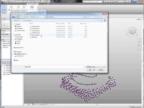
Further reading: One of my team recognised that the point pattern was very similar to an error that occured in Geomagic. very similar to how Revit has issues with things being too far from project base point so does geomagic. It turns out that even though I dropped the cloud very close to the project base point for some reason Revit 2014 must be still reading the old real world coordinates and sees it as if it is still 100s of miles from origin, which is what seems to be causing the resolution problems. Hence we went back into the original registered data in cyclone and made the project arbitrary (moved it close to 0,0,0), we then re-exported to .pts bought into Revit and the results are as per the attachment, loads better than before and deffinately possible to work with now!via RevitCity.com | Revit 2014 Point Cloud Benefits/limitations?
If you are working with point clouds, you are probably aware that setting up the points to be re-modeled properly within Revit is essential. When you import your point cloud by shared coordinates, you are left with a 3D model of your points. via Setting up your Revit project to model point cloud data | BIMopedia
On Revit 2014: The new point cloud engine uses RCP/RCS formats. The RCP format is a project file while an RCS file is a scan file. A RCP file is a group of multiple RCS scan files. If you have raw data in other acceptable formats Revit will index it in the background and let you know when the indexing is complete. … They enhanced Revit’s sensitivity to points and planes within the point cloud data. This should make it easier to sketch model elements using the underlying cloud data. Revit will detect planes that are perpendicular to the current work plane and very close to the cursor. via Revit OpEd: Point Clouds in Revit 2014
For some time, I have been looking for a way to get 3D geometry from any format, make it into a nice, Revit-friendly SAT and then use it in massing or visualizations. Can Memento help me with this? Answer – not really.
What it can do:
Import and Export formats: OBJ and RCM (Recap)
allows users to easily (?) fix meshes for digital use or fabrication
fix topology or texture issues (holes, spikes, tunnels, particles, etc.) prior to downstream use
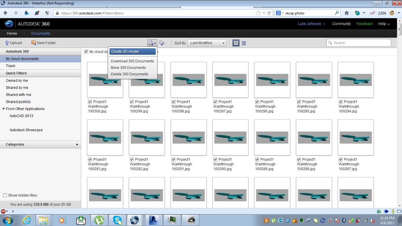
I realised at this point that you can’t make an RCM file from Recap… What a pain! So, looks like we need to make one using Recap Photo. To use Recap Photo, upload some images to Autodesk 360.
This time, I sort of succeeded by:
Importing an interesting model into Revit
Making a Walkthrough that circled the object, and exported to a set of JPGs
Uploaded them to Autodesk 360
Selected them and clicked on the little Create 3D button (only 250 images will be accepted for processing)
Waited overnight for the model to process…
Opened Autodesk 360 and downloaded the file .obj.zip
Now, use Memento to open and edit the OBJ – and try to fix the holes in it.
My first experience with Memento wasn’t great … I was expecting a Fix All button 🙁
Opened the OBJ in Memento
Click find defects (middle of top of the screen)
After they are found, click next or previous, then click Fix
Rinse and repeat thousands of times
Note: Memento will not run on Windows XP.
Heads-up via
Here’s the Labs link to download Memento. Is this the end of gift shops with miniature trinkets (lets hope so)?http://t.co/meq6XPnaCO — Sean David Burke (@seandburke) August 8, 2013
The E57 specification uses a subset of XML that has been extended to support efficient storage of large amounts of binary data. An E57 file is encoded as a hierarchical tree structure, some of which is encoded in XML, and some of which is encoded in a binary format that is not XML. The bulk of the data, including point data and images, is encoded in the binary sections for efficiency. Metadata, such as sensor pose information, is encoded in XML. The binary sections are not embedded in the XML section. Instead, they are located in separate sections of the file and referenced from the XML section.
Is the E57 format extensible?
Yes. One of the greatest strengths of E57 is that it was designed to be readily extensible to accommodate new hardware innovations.
How does this all fit in with Revit? … Revit 2014 does support the import of E57 through the new Recap software released a few weeks ago. The primary idea is that by using E57 you will have support for nearly all of the laser scanner vendors’ data since they can write an E57 file and Recap can read it. That will allow you to import it and then convert it to a Revit format to use the data. It’s a data exchange format, not a working format. We are now trying to recruit some new people the ASTM E57 committee who can help us define and move forward on a number of extensions to the basic format. (above paragraphs via email)
Could we laser scan the world, make a big point cloud, and then import it into Revit? Well, one day we might be able to accomplish that on a small scale (then again, maybe not). In the meantime, try this process:
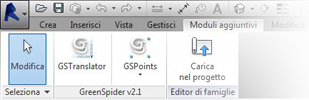
It is an interesting add-in for Revit that can import point data into the conceptual environment. It was written to “narrow the gap between computational concept design, terrestrial laser scanning and Building Information Modeling.”
Video:
Download page Version 2.1 has just been released (25 May 2013)
Some info: GreenSpider conveniently parses ASCII text files representing 3D vertexes, whether generated by computational modeling software or terrestrial laser scanning equipment.
Once installed through this installer package on Windows-based pc’s, GreenSpider 2.1 can be accessed in Revit mass modeling environment. … GSpoints and GScurves. The first one simply imports vertex point cloud as reference points in mass modeling environment, while the second traces a spline interpolation among imported points sorted through a TSP process, in order to build surfaces after recursive .GSP imports.
… Decimated laser scanner point clouds are imported this way in Revit as many times as needed (using a reset function every time in Translator module), and generated curves can be used to originate surfaces very close to their real geometry.
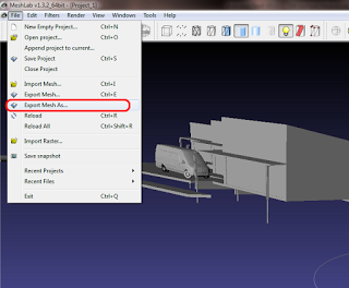
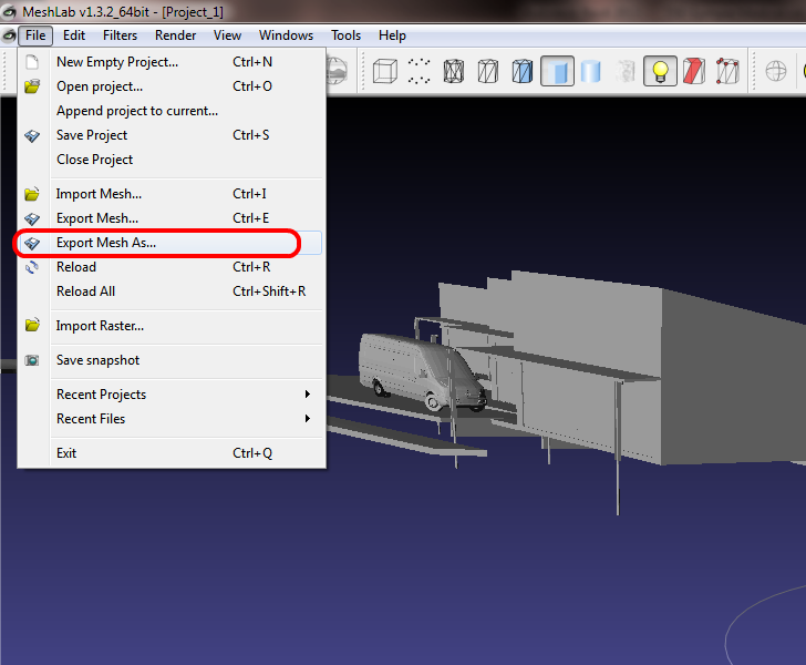
Point clouds are getting a lot of “press” lately, and they can be very useful. But let’s say, hypothetically, that you have a 3D model of a building or a component and you want to deconstruct it back into a point cloud – Can this be done? Yes, and quite easily…