Revit doesn’t like big numbers. There, I said it.

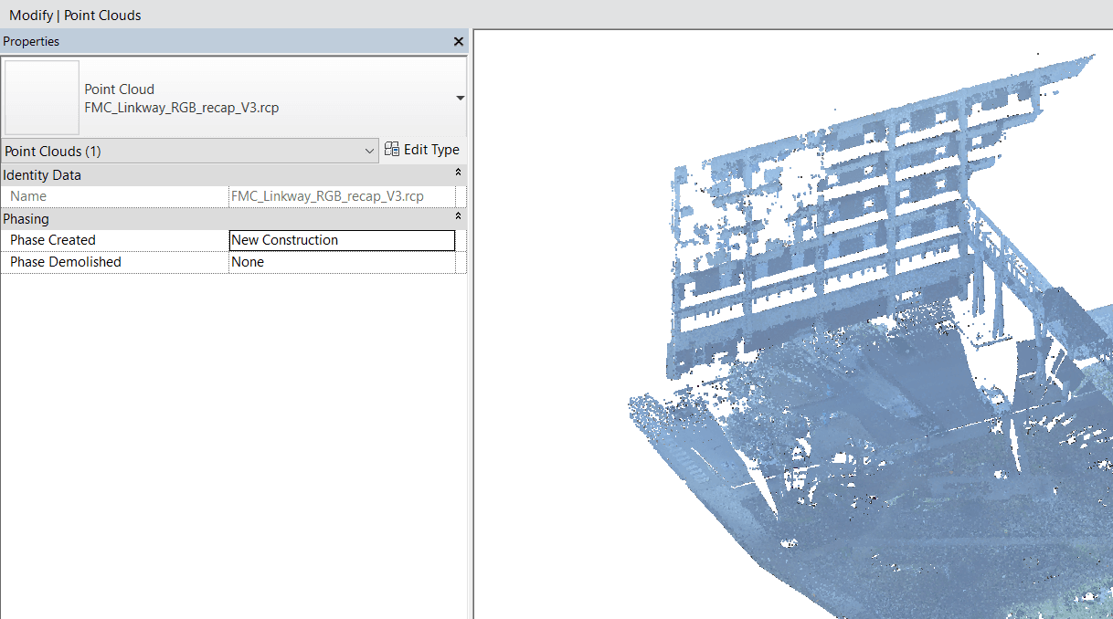
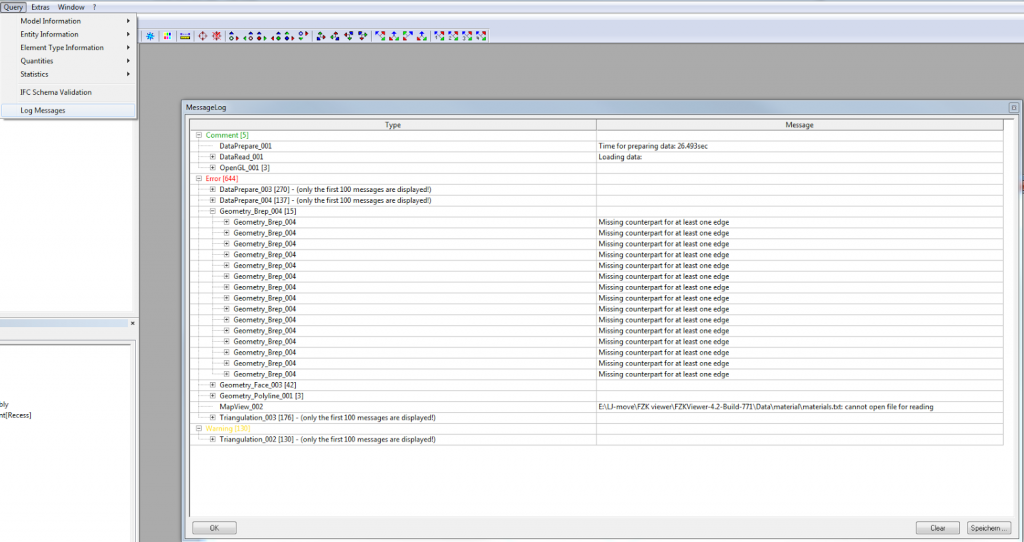
So when dealing with ‘world’ coordinates in a point cloud, sometimes things just don’t work too well. I thought I had this all solved recently by using the DXF, Center-to-Center, Acquire Coordinates workflow. However, I discovered that somewhere along the line, Revit still does break down with the large coordinates. I think this is happening in between Recap and the Revit point cloud rendering engine. I was getting something that looked like this:

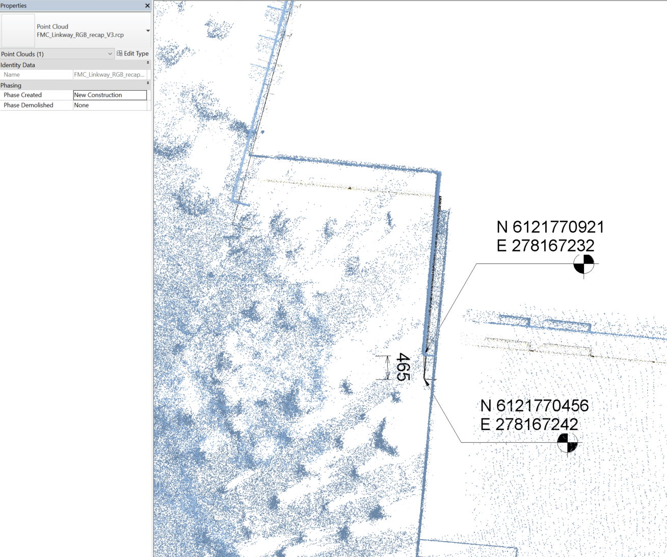
As you can see, the shared coordinate system is very large. In this situation, you can’t even move the point cloud into the correct location in Revit, it jumps in large increments when moving. Interestingly, Navisworks and AutoCAD both handle these large coordinates ok – appending the same data does not have the error shown above. So…

How do we fix this and make Revit happy?

Basically, we do a temporary truncation of the source data, get it into Revit, and then reinstate the appropriate coordinate system.

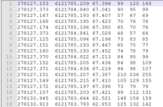
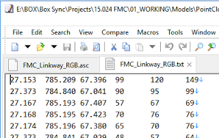
To truncate the data, have a look at your source point cloud information. In my case, I could identify 4 leading digits for the X and Y coordinates that were not significant:

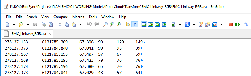
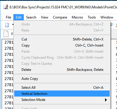
Using EmEditor (which handles large text files very well), and its Vertical Selection feature, I was able to delete the 2781 and 6181 digits from my source data.

In effect, this transformed everything by 278100m and 6121000m. Keep these numbers in mind for future reference…

simplified.png

Ok, with the simplified source data in hand, I followed these steps:

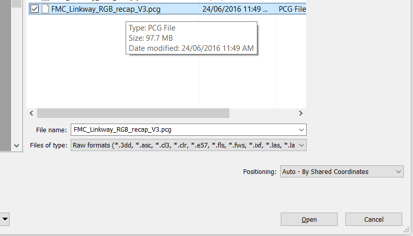
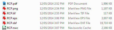
  1. Index a new RCP in Recap using the simplified data
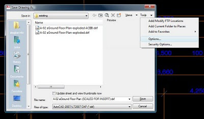
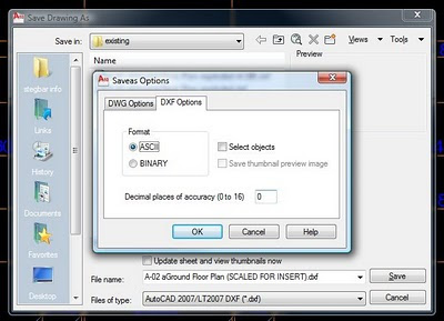
  2. Open surveyor DXF file in AutoCAD and manually Move all the geometry. Move the objects by the values above (278100, 6121000) towards the origin. Save As – a new DWG file with modified coordinates.
  3. Link this modified DWG into Revit, Center-to-Center
  4. Acquire Coordinates from it
  5. Link the Point Cloud RCP By Shared Coordinates
  6. Everything lines up now that the large coordinate shift error has been avoided!
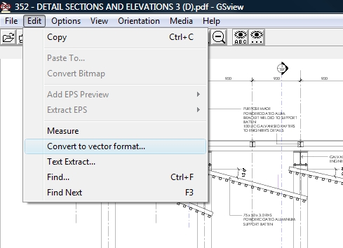
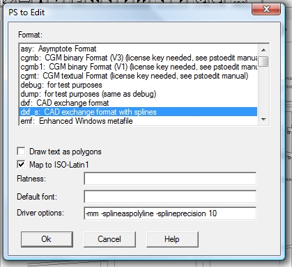
  7. Link in the original DXF and align it with the modified temporary DWG we were using
  8. You may need to temporarily neutralize coordinates (here or here), and…
  9. Now you can Acquire Coordinates from the original DXF and you will have reinstated the ‘world coordinates’, but the Revit point cloud rendering engine is now much happier.

Hope this helps you if you face a similar problem 🙂

Previous post:
What Revit Wants: Using a DXF to Locate a Point Cloud in Revit with Very Large Coordinates

I thought that most of this was ‘easy’ and solved now, but it was more of a challenge than I expected. I received a ASC file from a survey in XYZRGB format, which looks like this:

asc.png

Those XYZ values are Metres (or Meters if you are in US) in the MGA 94 coordinate system. I also received a DXF file with the same World coordinates, and project related gridlines so I could relate the point cloud to our Revit models.

I tried getting the MGA Shared Coordinates right in Revit, and then linking an RCP or RCS from Recap ‘by Shared Coordinates‘, but I didn’t have much joy.

Here is the workflow that worked for me…

Getting the right Shared Coordinates in Revit

  1. Start a new, blank Revit model
  2. Link the DXF Centre-to-Centre (this is best way to deal with huge coordinates)
  3. Acquire Coordinates from it
  4. Save your Revit file. You now have the right World coordinates, and a project grid relationship.

Importing the Point Cloud by Shared Coordinates 

  1. Open Recap and import the data. For the ASC data above, on the import settings I used ‘Advanced’, and chose the text columns XYZRGB. I also set the coordinate system.
  2. Export to PCG. Sounds weird, I know. But PCG is a nice reliable container that supports colours.
  3. In Revit, Link Point Cloud, by Shared Coordinates, and choose the unIndexed raw PCG:
     
  4. Revit will now open another dialog, and you can index the PCG file (again) to an RCP+RCS
  5. Link this RCP file by Shared Coordinates
  6. It should be in the right location and related to the DXF coordinate system.

Many of us use Tekla BIMsight or Solibri for IFC viewing, but there is another free option: FZK Viewer. It is just a 10mb download, unzip and go.

It has a Walk tool like Navisworks for easy navigation, and it can even export to a number of formats, including:
DXF (cool! quick IFC to DXF conversion anyone?)
VRML 2
STEP
Collada
Google Earth
CityGML

Additionally, it can open gbXML and GML files. All in all, a handy piece of software to have if you are dealing with IFCs on a daily basis.

Oh, did I mention it can Merge .xyz point cloud files to the scene?

Build 771 direct link:
http://iai-typo3.iai.fzk.de/www-extern-kit/fileadmin/download/download-vrsys/FZKViewer/FZKViewer-4.2-Build-771.zip
On opening an IFC, it produces a log file that can quickly locate geometry problems:

Download page:
http://iai-typo3.iai.fzk.de/www-extern/index.php?id=2315&L=1

Main page:
FZKViewer

We often have to deal with data that hasn’t always “lived” in our CAD, BIM or Revit world. Take a hand sketch, for example – how can you get that into a format that can easily be used in AutoCAD or Revit? Some PDFs have vector information, which I have described how to access before. But the below workflow takes it one step further – how to get any raster image into a vector format, using a few free tools.

Here’s how to do it, without Adobe Illustrator:

  1. Make your source file (PDF / Scan etc) into bitonal TIFF image (I use Bluebeam and Irfanview in the video, but you could easily save the PDF to image using GSView)
  2. Open in Inkscape
  3. Vectorize using Path – Trace Bitmap… Brightness steps, set to 2.
    Untick: Smooth, Stack scans, Smooth corners and Optimize paths.
    (this step makes the black and white image into lines and outlines)
  4. Save as EPS
  5. Open in GSView (requires Ghostscript and pstoedit)
  6. Save as DXF (using Convert to Vector format). From here, you can get to AutoCAD or Navisworks easily…
  7. Open in AutoCAD
  8. NWCOUT and/or
  9. Append the DXF directly to Navisworks
  10. Scale and position appropriately

Here’s a quick video of the process:

The file sizes at each step look like this:

In Google Docs, you probably know that you can upload files and view them with the Google Docs Viewer.

But did you know that Google Docs Viewer can display the following formats?

  • Apple Pages (.PAGES)
  • Adobe Illustrator (.AI)
  • Adobe Photoshop (.PSD)
  • Autodesk AutoCad (.DXF)
  • Scalable Vector Graphics (.SVG)
  • PostScript (.EPS, .PS)

If you want to view something online, just put the URL of the file in at the following link:
Google Docs – Viewer

For a more complete list of filetypes, check out this link.

Sometimes you will have access to a PDF file, but not to the original DWG.  Is there any way you can get the base vector data, such as lines and arcs, out of the PDF and back into a DWG?  Yes, there is – and it’s free.

You will need 3 things:
Ghostscript or here
GSView
pstoedit (or Windows exe link here)

Download and install each of the above tools.  Make your life easy and stick with the 32-bit version of everything.

Once you have installed them all, open a PDF file using GSView.  GSView is usually located in  
C:Program Filesghostgumgsviewgsview32.exe

With your PDF open, take the following steps:

  1. Click on ‘Media’ and set the correct paper size.
  2. Go to ‘Edit’ and click on ‘Convert to vector format…’
  3. At the resulting PS to Edit dialog box, choose dxf_s, and add the following Driver options:
    -mm -splineaspolyline -splineprecision 10
    (I have found these settings to work quite well)
  4. Click OK.
  5. Select the page in the next dialog (usually only 1), press OK, and then pick a place to save the DXF file.
  6. Click Save.
  7. Open in AutoCAD and scale to correct size.
  8. Save as DWG.

If you have any problems, feel free to comment and I will try and help you out.  If you intend to import the DWG into Revit, keep in mind that Revit is not very impressed with very short lines.

Enjoy your PDF hacking!

Let’s say you have AutoCAD file of unknown origin, and it has some wacky or imprecise units (like the distance between two walls is 8250.092234897). What you need to do is reduce the precision, such that all the decimal points get ‘chopped off’.

To do this:

  • Open the offending DWG in AutoCAD.
  • ‘Save As’ and choose a DXF format.
  • Go to Tools menu – Options (see below)

  • Choose DXF Options, ASCII Format and set the ‘Decimal Places of Accuracy’ to the desired value (choosing 0 will remove all decimal places):

  • Hit Save.

I recommend that you now open the DXF file you saved, and then resave it as a DWG file.Now you can insert your file into Revit, and you won’t have to deal with imprecise units.Please note that this process may result in some ’rounding off’ of values – you may want to double check the resulting file.

I found this process at the following link:
Forum Link