You have a Revit file with some custom hatch patterns (filled regions / fill patterns) in it. You want to turn them into PAT files for re-use in AutoCAD or some other drafting program. Here’s how:
- Make a Drafting View in Revit with a couple of Filled Regions in it.
- Set the filled Regions to the Revit Hatch Patterns that you want to export to PAT files.
- Export the Drafting View to a 2000 version DWG file
- Open the DWG file in AutoCAD
- In AutoCAD, APPLOAD then browse to getpat.lsp file. To get this file, right-click and Save Target as from this link.
- After loading the lisp file, File – Save As the DWG, to something in the same directory (this step just makes AutoCAD and the LISP aware of where the PAT files should be saved)
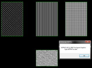
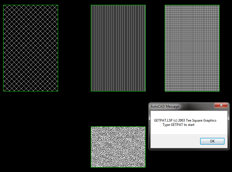
- Then, type GETPAT
- Select the hatch you want to export. It *should* be saved as a PAT file to the same directory that the DWG file is in.
EDIT – you could also try this method:
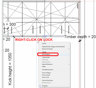
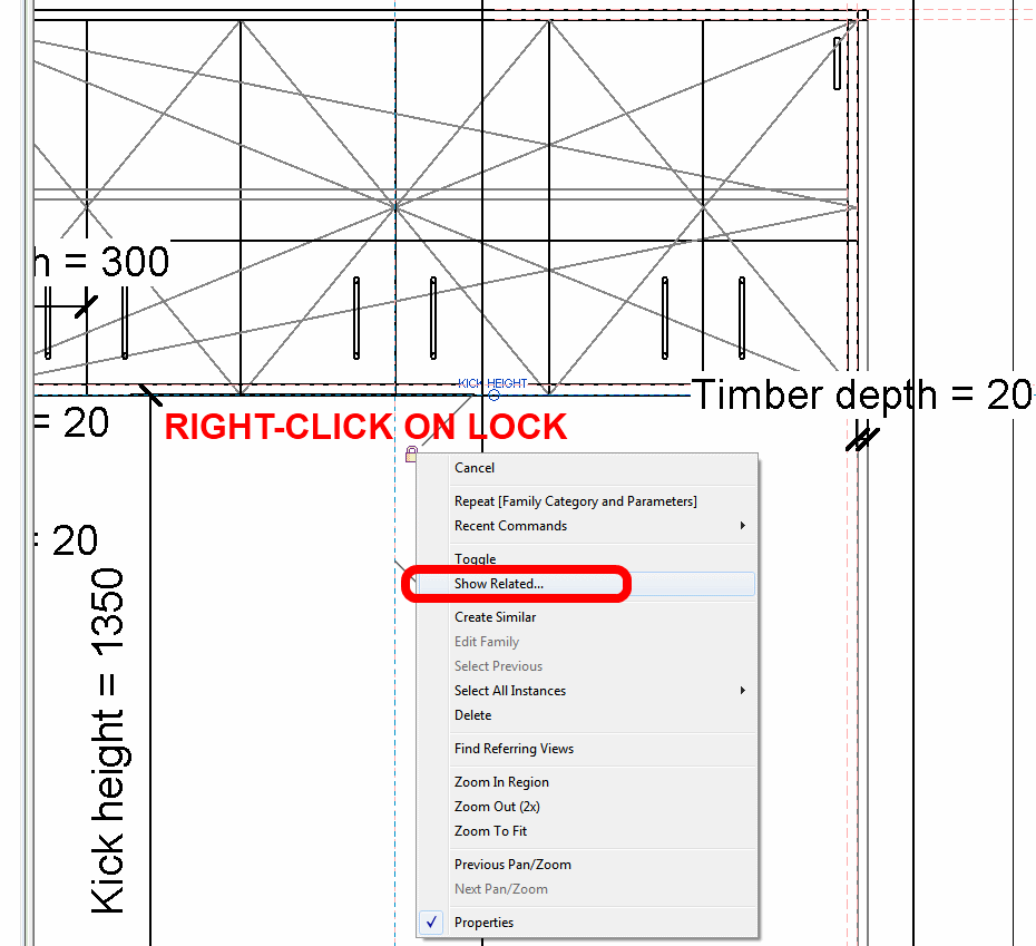
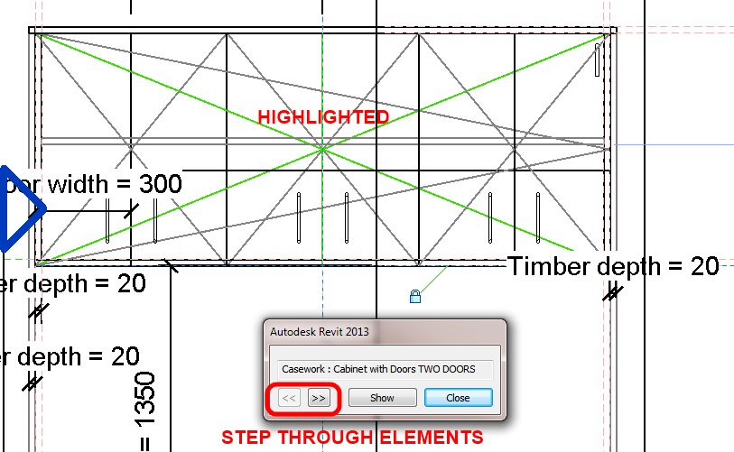
What Revit Wants: Native Revit can make PAT files too – you just have find them …
In response to this tweet:
Would be nice if you could get the pat files back out of a #Revit file…
— Jason Rostar (@jrostar) September 17, 2012
Related forum post:
http://forums.augi.com/showthread.php?71833-Creating-a-pat
More free lisps:
http://www.turvill.com/t2/free_stuff/index.htm


 I made this one in less than five minutes from scratch. Not much more work than the old in-place deal. Make a few versions and you’re “done”.