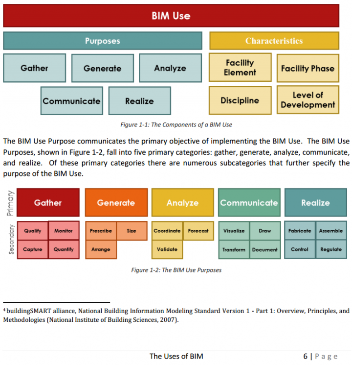
To oversimplify, this document essentially forms a categorized glossary of terms that show how the BIM process works and what kind of information is generated by it.

Excerpt:

Download it at:
http://bim.psu.edu/Uses/the_uses_of_bim.pdf
by RALPH G. KREIDER AND JOHN I. MESSNER

Heads-up:
http://revitlandscape.blogspot.com.au/2014/01/the-uses-of-bim-classifying-and.html

Probably the browser one is the most interesting…  Oh, is it only me that finds the misspelling of accuracy quite hilarious 🙂

 JT Import Add-in
Enables JT files to be accessed from within Design Review with full fidelity and accuracty.

DGN Import Add-in
Working with DGN? Now Autodesk has a add-in for Design Review to enable importing of DGN files, making your design review process more seamless.

Autodesk® Design Review Browser Add-in
The Autodesk Design Review Browser add-in for Autodesk Design Review software lets you view DWF™ files using Mozilla® Firefox® and Google Chrome for the Windows® operating system. Now, you can view embedded DWF files in Firefox and Chrome much the same way as you do in the Microsoft® Internet Explorer® browser.

Source:
http://usa.autodesk.com/adsk/servlet/index?siteID=123112&id=13635915&linkID=9338138

Using Schedules, you can usually use Highlight in Model to find an element (or group of elements) from a schedule row.

However, this does not work if the element is hidden in the only view that it is instantiated in – for example, a single Generic Annotation entry in a Note Block (Schedule).  Revit will not be able to find the element.

One workaround – interestingly, selecting a Schedule row actually selects the object/s in Revit, but at least in my configuration (Properties Palette on second monitor), it does not show the Properties in the Palette for that object while the Schedule view is active.  However, you can:

  1. Select the schedule row
  2. Switch to another view (for example, a 3D view)
  3. The Properties Palette has now updated to show the properties for the Element!
  4. You can trigger normal commands – such as IDs of Selection or Save Selection

Another workaround:

  1. Install RevitLookup
  2. Select the row in the Schedule
  3. Revitlookup – Snoop Current Selection… (this will give you Element ID and other info)

From a post by Stephen Blacklock:
In early 2013 we started work on a live full-site BIM project …

Agreeing the deliverables at the outset (and being totally truthful about what we could actually deliver) was key…

Complex areas of level changes were resolved very early in the design process, when I know these could have been problem areas on site. 

Our planting plans were also delivered in a BIM compatible environment linking the planting plans into the 3D project model and providing visual understanding of massing. 

All hardscape materials in the model included construction build ups and specification details integrated to the model as does all site furniture, fencing and walls. 

Sections and schedules are generated directly from the model reducing the risk of errors and ensuring all project information is aligned.

Read more:
BIM and Landscape Architecture | Knowledge

Interesting post by Ben a while back on the impact of Revit view settings when exporting to Navisworks.  In most cases, this is “logical” – if you can see it, it will get exported, but if you can’t see it, then it won’t.

However, this doesn’t quite hold true for model lines.  Have you ever wanted to export model lines (3d) from Revit and import these into Navis?  Ben suggests this workaround:
Model lines will not be shown in your 3D Navisworks file when brought through from your Revit project. One way to combat this would be to export your Revit file as an .IFC and then bring that file into Navisworks. .IFC brings through model lines but not detail lines through the { IfcAnnotation } Parameter.

 via
http://bimopedia.com/2013/11/25/view-settings-from-revit-into-navisworks/

Check out the solution suggested by Andreas Dieckmann:

“I ended up using one of Python’s abilities to handle lists which is called groupby() because I did not want my head to hurt thinking about how to go about this in Dynamo… 😉
Here’s how:
  1. Sort list by X values using the method Steve explains above
  2. Sort list by Z values 
    (Notice that within each group of equal Z values, the X values retain their order from the previous sort operation)
  3. Create a list of lists with XYZ values (sublist 0) and just Z values (sublist 1)
  4. Group that list of lists by the Z values (using a custom node with some Python code inside)
  5. Extract only the list of lists of XYZs by combining two map nodes
You will need the package Group List of Lists By Key for this to work.
(For what it’s worth, I also uploaded another package called Sort List Of Lists this week which was related to that project but isn’t needed here. But it might be worth checking out, too.)”

Heads-up:
https://twitter.com/Jbenoit44/status/420673580838293504

Not all actions will be available in all circumstances…

When performing a coordination review, you can specify how to handle each change in the current project. To specify an action for a change, click in the Action column and select an action from the drop-down list. The available action values vary depending on the type of change.
Note: Actions that result in changes affect the current project only. They do not change a linked model.
Postpone/Do nothing: Take no action. This value leaves the change to be addressed at a later time.
Reject: Select this action to indicate that the change made to the element in the project is incorrect. Instead, a change must be made to the associated monitored element in the linked model.
Accept difference: Select this action to indicate that the change made to the monitored element is acceptable, and to update the relationship without changing the corresponding element. For example, suppose 2 monitored grid lines are 200 mm apart, and one is moved to 300 mm away. When you select Accept difference, the monitored grid lines are not moved, and the relationship is updated to 300 mm.
Modify: A grid line or wall centerline has changed or moved. Select Modify to apply this change to the corresponding element in the current project.
Rename: The name of a monitored element has changed. Select Rename to apply this change to the corresponding element in the current project.
Move: A monitored element has moved. Select Move to apply this change to the corresponding element in the current project.
Move Fixture in Host to Position of Fixture in Link: A monitored fixture has moved. Select this action to move a fixture in the host model to the location of the fixture in the linked model. This action only works for fixtures that are not hosted. If the fixture in the host model has been hosted on a surface using the Pick New Host tool, then selecting this action will display a Fixture is Hosted warning message.
Ignore new elements: A new hosted element was added to a monitored wall or floor. Select this action to ignore the new element in the host. It will not be monitored for changes.
Copy new elements: A new hosted element was added to a monitored wall or floor. Select this action to add the new element to the host, and monitor it for changes.
Delete element: A monitored element has been deleted. Select this action to delete the corresponding element in the current project.
Copy Sketch: The sketch or boundary of a monitored opening has changed. Select this action to change the corresponding opening in the current project.


Update extents: The extents of a monitored element have changed. Select this action to change the corresponding element in the current project.

via
http://help.autodesk.com/view/RVT/2014/ENU/?guid=GUID-2593470B-FBC9-49CC-9962-664D508B2B91

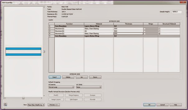
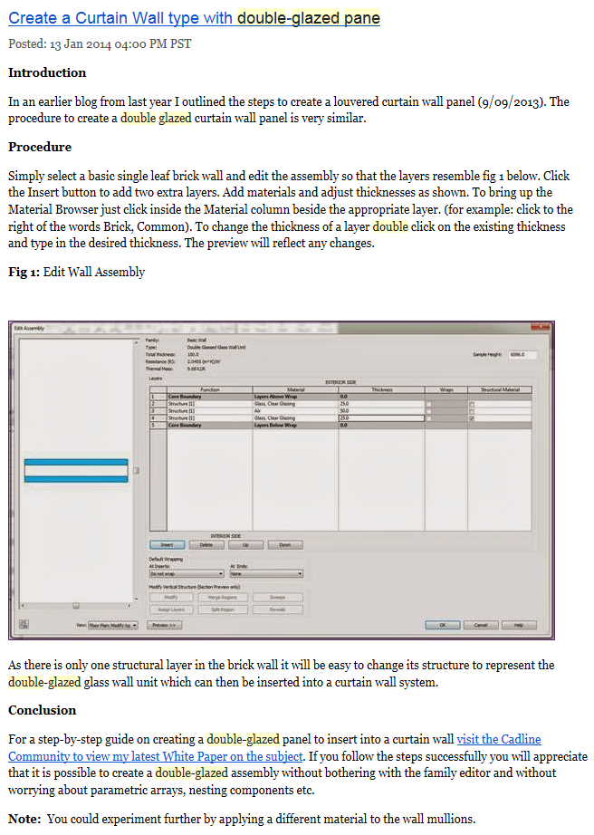
 John Flanagan details an interesting concept in a recent post – he shows how you can use a Basic Wall with two Glazing layers separated by a core layer to essentially model double glazing systems.

You then simply add this Basic Wall to a Curtain Wall type as the applied Panel.  Great idea!

Read the whole post at:
Create a Curtain Wall type with double-glazed pane – Blog – CADline Community

Link is dead so I have resurrected the content from archive:

I’ve always felt that the Floor tool in Scan to BIM is a bit lacking – rather than analysing and deforming an existing Floor element, I want it to work like the Topo tool (just select a bunch of points and decimate).

Well, now it can (sort of).  Like this:

  1. Use the Scan to BIM topo tool to make temporary topo “Floors”
  2. Then use the Topo to Shape Edited floor macro from Boost Your BIM

Sometimes, What Revit needs is for you to put two workflows together to solve a problem in the most efficient way…