A while back, I conducted extensive research into Revit content management tools. I was commissioned by Unifi to do this, and I told the story of the process over here. You can also watch the related webinar here. Over the last couple of years, some of you have approached me to gain access to the master Excel comparison matrix document that I produced. Recently, Jay Merlan updated this document on behalf of Unifi and it has now been approved for public release!
The document is very detailed and consists of a number of key sections:
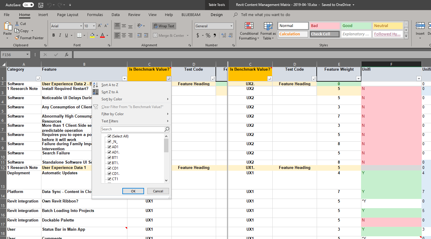
Matrix – where data is entered and initial scores are calculated. This includes a ‘feature weight’ where you can allocate how important a given feature is to you personally.
Screencasts – links to actually tests undertaken
Test Results – summary sheet
Cost data – a series of sheets for attempting to compare and calculate overall cost of the content management system
Summary Pivot Tables and Charts
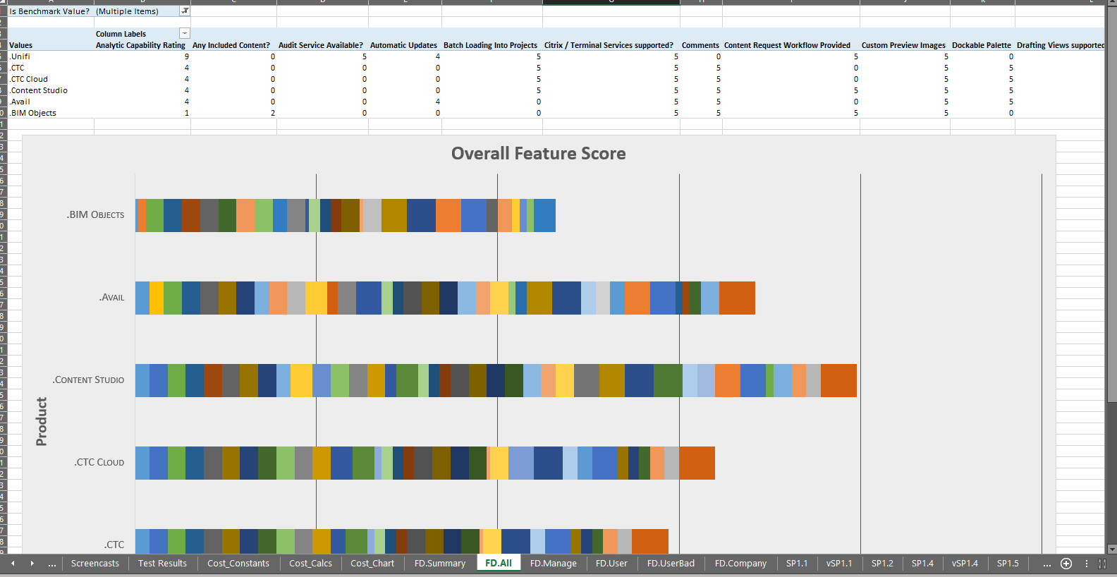
Overall Summary Chart
Summary PivotChart
As it is an Excel document using Formulas and Pivot Tables, it could be a very powerful starting point for you to dig in and investigate the various features of Revit and BIM Content Management systems and Content Providers. I hope you find it useful!
Feel free to comment here with any of your thoughts, and if you have any questions about the document and how it works.
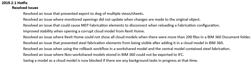
I have been resisting the 2019.2 update because there were some issues with it originally, plus the forced upgrade of Dynamo. I decided to go ahead with Revit 2019.2.1 Hotfix today. I think that the forced Dynamo update occurred with the 2019.2 major point version, but 2019.2.1 seems to install without forcing the Dynamo upgrade – on my machine, Dynamo 1.3.4.6666 was not updated during the 2019.2.1 hotfix installation. Here are the links:
If Revit 2019 and Revit LT 2019 are installed side-by-side and the 2019.2.1 Hotfix is only applied to one of these products, a “Could not load type ‘Autodesk.Revit.DB.ICloudExternalServer’ from assembly” error will be displayed when launching the non-updated product. To alleviate this error, make sure to apply the 2019.2.1 Hotfix to both Revit and Revit LT in side-by-side configurations.
Having recently installed some more storage hardware, and previously posted about moving folders with symbolic links, I then decided to move my BIM 360 Glue cache folder and Navisworks Cache folder to a secondary hard drive. I did this using symbolic links.
You need to:
start a Command Prompt as Administrator
use the commands shown below
Moving BIM 360 Glue cache storage location:
if exist "%localappdata%\Autodesk\Bim360Glue 2016\LocalCache" rename "%localappdata%\Autodesk\Bim360Glue 2016\LocalCache" bim360glue2016.old
mklink /d "%localappdata%\Autodesk\Bim360Glue 2016\LocalCache" R:\BIM360Glue2016
if not exist R:\BIM360Glue2016 MD R:\BIM360Glue2016
robocopy /mir "%localappdata%\Autodesk\Bim360Glue 2016\bim360glue2016.old" R:\BIM360Glue2016\
Moving Navisworks cache storage location:
if exist "%localappdata%\Autodesk\Navisworks 2019\LocalCache" rename "%localappdata%\Autodesk\Navisworks 2019\LocalCache" Navisworks2019Cache.old
mklink /d "%localappdata%\Autodesk\Navisworks 2019\LocalCache" R:\Navisworks2019Cache
if not exist R:\Navisworks2019Cache MD R:\Navisworks2019Cache
robocopy /mir "%localappdata%\Autodesk\Navisworks 2019\Navisworks2019Cache.old" R:\Navisworks2019Cache\
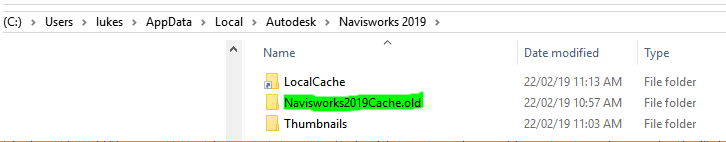
After you have run the scripts above, you can delete the old folders with the .old suffix (Navisworks example shown below).
Revit Users do a lot of funny (and sometimes quite terrible) things. BIM Managers have spent years trying to control the chaos, through training, documentation, standardisation, model auditing, Big Brother techniques, and a mixture of carrots and sticks. And that is why I really like the idea of Guardian.
Ultimately, people just can’t quite be trusted to comply with all the constraints you think are valuable. But if you have a ‘virtual firewall’ for Revit, it should take the human element out of the equation, right? The idea is that your Revit model is a secure and safe place – a lot of important work happens in there, so you don’t want it to get infected with junk. It is harder to remove the junk later, than it is to programmatically STOP the bad stuff from entering your model. Enter Guardian for Revit…
Have you ever wanted:
To restrict users from exploding CAD, modeling in-place, etc.?
To prevent users from creating duplicate properties?
To automatically clean content that users bring into projects?
A better ‘purge unused’ tool that cleans object styles, patterns, etc.?
To translate content to meet different requirements / standards as it enters projects?
To quickly align your library and details into complete conformity with your template?
I recently had the chance to interview Parley Burnett, the creator of Guardian. Parley has had a lot of experience with Revit and content management over the years, and he offers some great insight below as he describes the ‘journey to Guardian’.
LJ: What motivated you to create Guardian? PB:
Revit can be so fun to work with and… not so fun. We understand the issues that cause inconsistencies in data and graphics and believe we should tackle them on a fundamental level before we can REALLY benefit from all that BIM can offer. We need a ‘new class’ of cloud powered assistants in our BIM environments as the old approach of adding complication (most other add-ins) to solve complication isn’t working. I have also tired of “standards” discussions never materializing and have come to believe that we can do this in smarter ways than maintaining spreadsheets and documents.
LJ: What key problem does Guardian currently solve? PB:
Cluttered properties in projects!!
Without Guardian, anybody can do anything at any time in any Revit project anytime and, as a result, administrators are forced to react rather than anticipate the resulting damage. Without intense oversight, Revit projects can quickly become a quagmire of properties such as materials, patterns and parameters. This causes confusion and friction as projects progress and deliverables can be messy.
Revit offers little assistance as many of the property types cannot even be purged if they are unused. Worse yet, administrators have no way of knowing WHERE these properties are used so and if they did, the cleanup would take far too much time.
Guardian allows complete transparency into incoming properties including whether they are used or not used. It then allows properties to be mapped to existing properties or removed. These decisions can be saved as rules and enforced silently across an entire firm.
LJ: What is coming up on the Guardian feature roadmap?PB:
We have hit several releases already since launching late last summer and are only picking up the pace even more! We expect to add more ways that Guardian can be extended to existing projects and more flexibly across project teams and user roles.
Here are some new things in Guardian 1.4.0:
Ability to detect duplicate properties
New Suggestions Framework
User prompts when duplicates are made or modified
Below I have included some how-to guidance information in the following sections:
Installation
Configuration
Using Guardian
Installation:
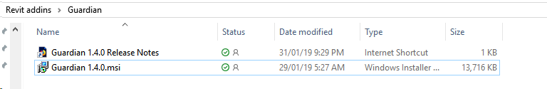
In the download package, you will get an MSI and current Release Notes:
Just double-click the MSI to install.
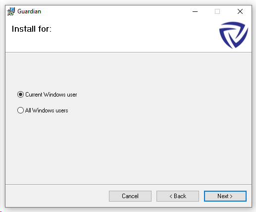
You can install for Current User or All Users:
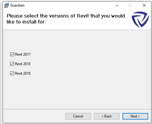
And choose from supported Revit version:
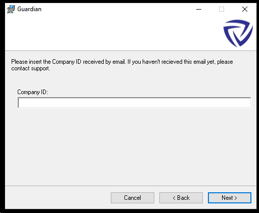
License activation is achieved by entering your Company ID during installation:
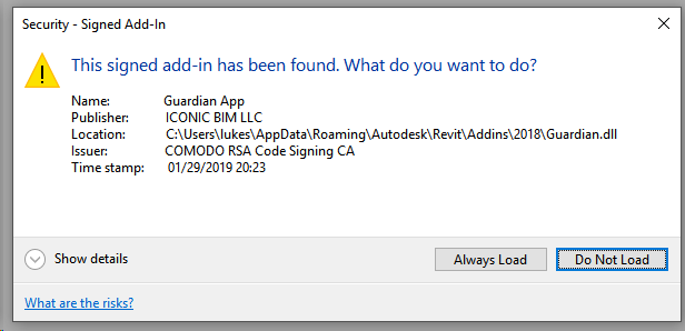
When launching Revit, you can press ‘Always Load’ at the normal security prompt:
Configuration:
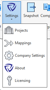
To manage your Revit content standards in Guardian, you use the ‘Admin Login’. Following this, you will see more features in the menu:
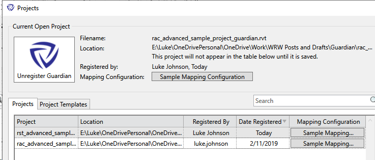
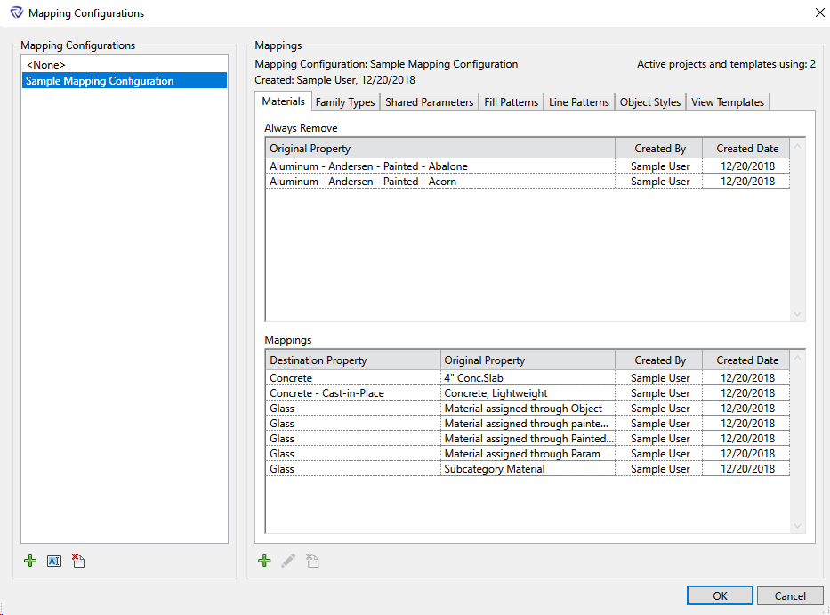
In Projects, you can define mapping files for each project, and you can create Project Templates:
The Mappings dialog provides the real ‘nuts and bolts’ of Guardian, you can individually configure constraints around the following items:
Materials
Family Types
Shared Parameters
Fill Patterns
Line Patterns
Object Styles
View Templates
It basically works by taking some incoming data from whatever source, and mapping it to the ‘project template’ or standard Revit libraries that you have implemented in your firm.
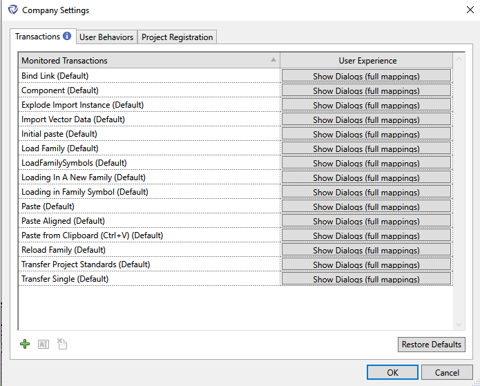
There are some really interesting features in the ‘Company Settings’, and this is where it really starts to take control of the human element I mentioned earlier:
When do you want Guardian to take action?
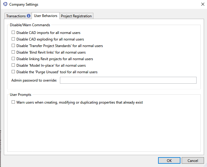
In ‘User Behaviours’ you can actually stop or restrain certain commands from executing. Evidently, Guardian makes a distinction between ‘normal users’ and admin-level users:
Using Guardian:
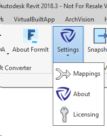
It will appear in your Add-Ins ribbon like this:
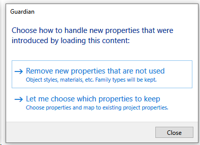
This is what happens when you load a new family:
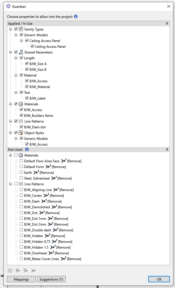
And this is what happens if you select “Let me choose which properties to keep”:
As you can see, you then have the opportunity to enter the Mappings dialog.
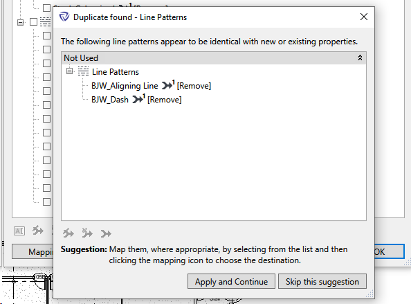
“Suggestions” will dig deeper into the content and let you know if certain things are similar or identical (very cool, it feels a bit like AI):
We have come a long way at Virtual Built Technology through building our VirtualBuiltApp federated project-wide data platform in recent years, and Guardian is an excellent accompaniment to it. As a company-level control mechanism, it aims to prevent the problems that can be detected later through our analytical methods.
If you are in a situation where you would like to really improve the overall quality and consistency of the Revit modelling in your firm, I recommend that you check out Guardian.
Ever since I bought it, the Metabox occasionally began screaming at me by way of extremely loud internal fans. As we know, cooling equals performance in laptop devices. If its not cool, it will ultimately either scale down performance through CPU throttling, or the effective life of the components will be adversely affected.
Up until today, I have been using this cardboard box and timber stud cooling device:
The Wii U box and timber stud laptop cooler
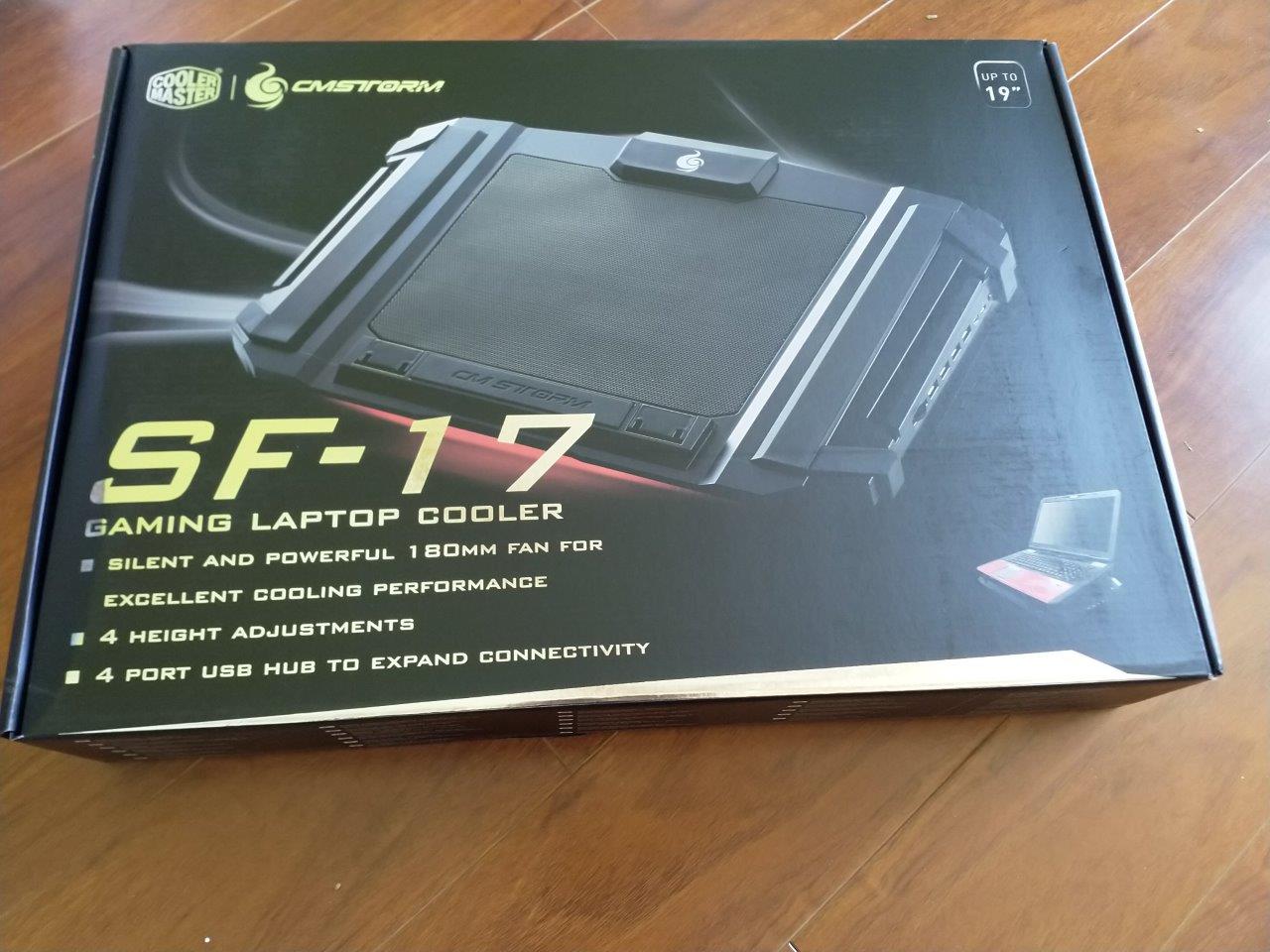
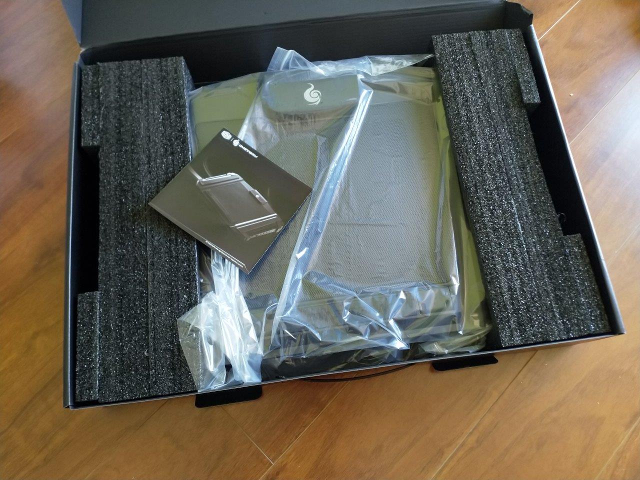
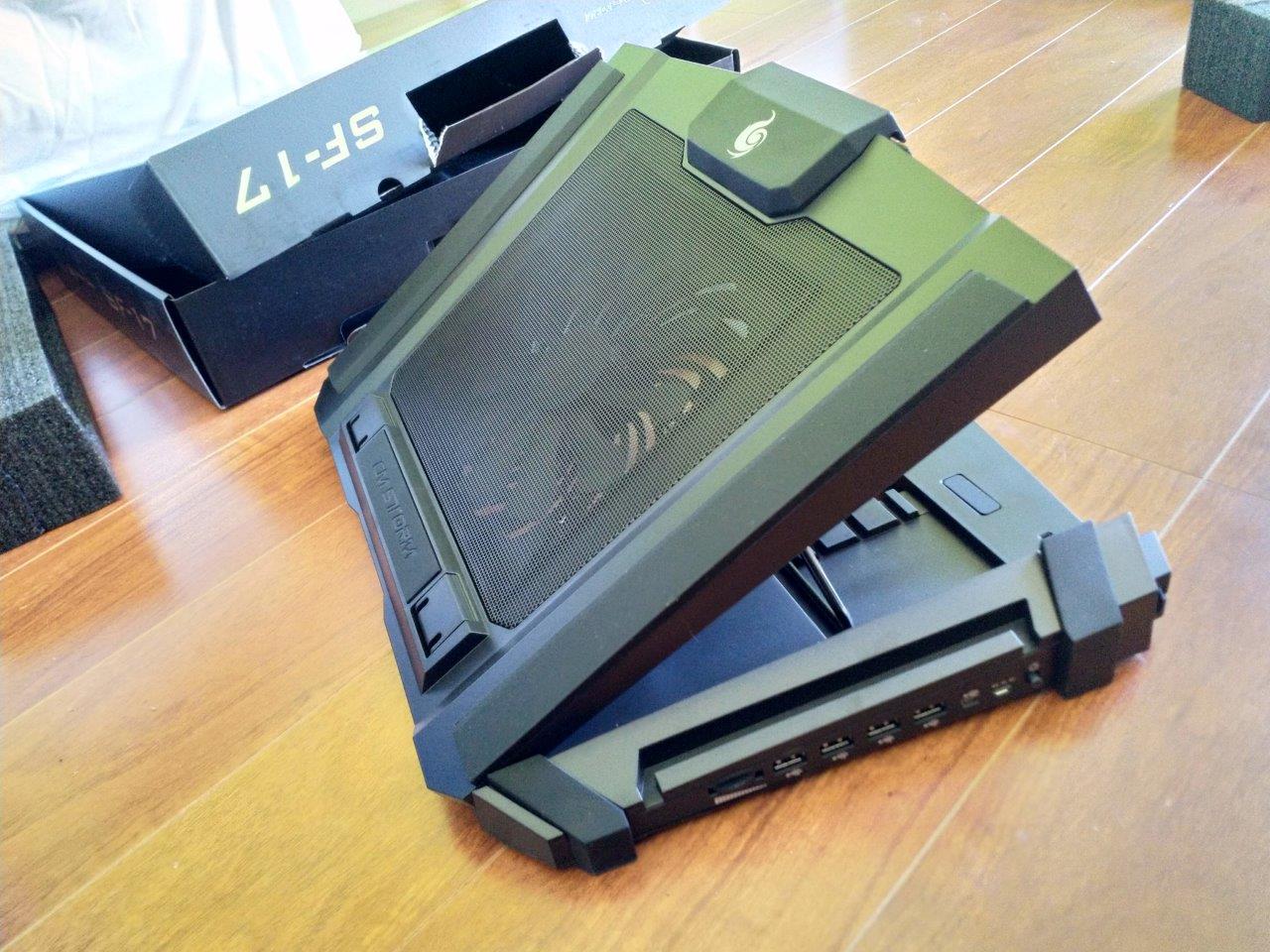
As good as the above solution was, I believed that it might be possible to reduce the decibel rating and extend the life of my laptop… so I was moved to purchase a ‘gaming laptop cooler’ – basically a laptop base with an integrated fan. I chose the CoolerMaster CMSTORM SF-17. This has one large turbine fan, and includes height adjustment and an inbuilt USB hub.
CoolerMaster CMSTORM SF-17 Unboxing #1
Unboxing #2
Unboxing #3
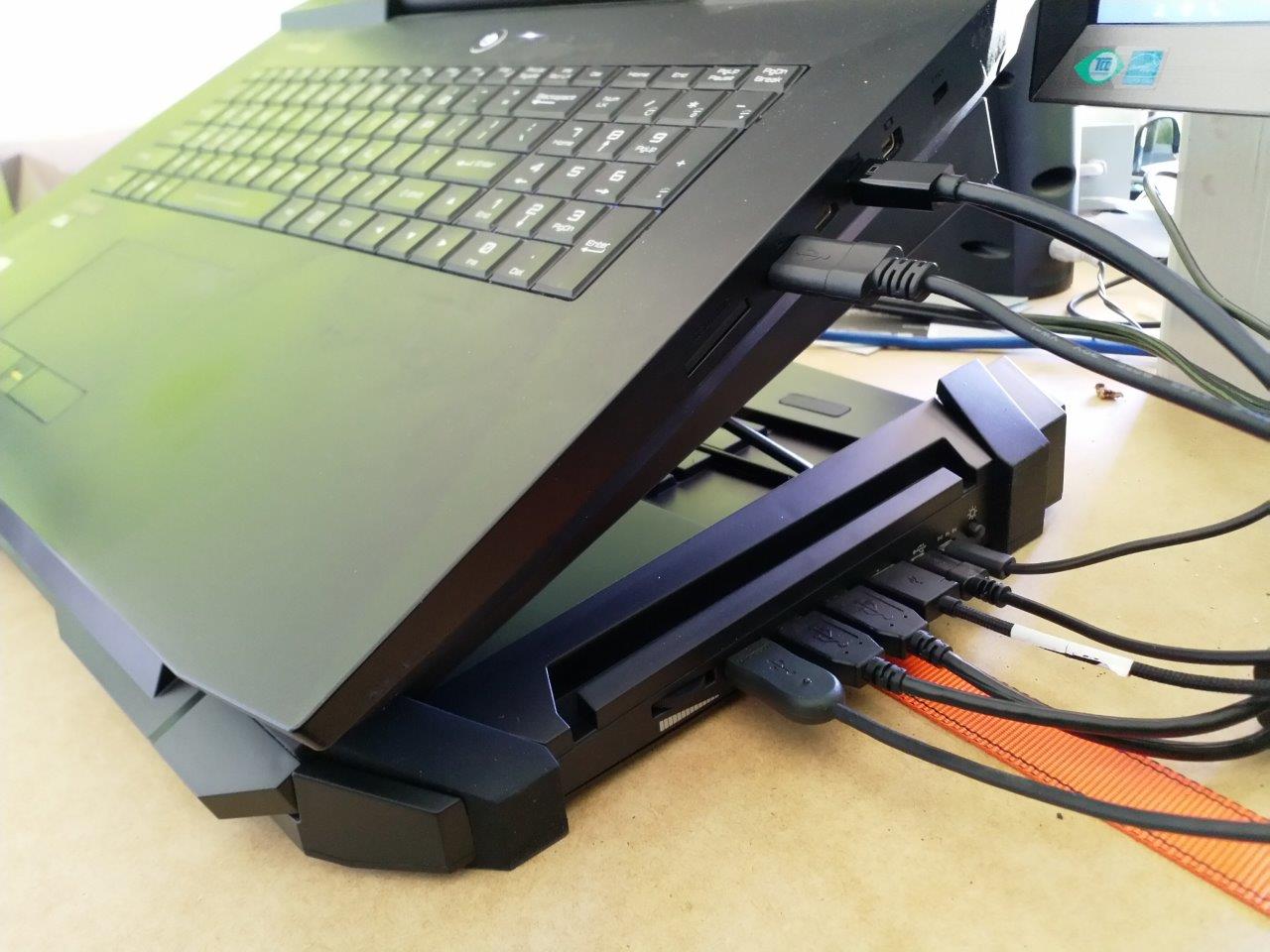
The new solution is much quieter and neater, and hopefully will give the Metabox ‘tank’ some extra longevity:
Box is great, and Box Sync is still the most robust file sync tool I have used for huge datasets. In BIM and VDC, our data is getting bigger, primarily due to the prevalence of point clouds. It is not uncommon to have 50gb of scan data for a single site scan. Moving that data to the cloud is challenging, and a lot of data processing and point cloud indexing work still happens on local machines. This means we have to upgrade our local storage devices (hard drives) to handle those tasks.
Recently I went about upgrading the storage on both my Workstation and my Laptop (a Metabox). I wanted a relatively huge platter drive in my workstation, and a relatively huge SSD in my laptop. I had a look online and after a bad experience with Umart, I ended up buying an 8tb Seagate Barracuda from MSY, and a 2tb Samsung 970 EVO from an eBay vendor. Both drives come with a 5 year warranty.
I’ll describe both of these upgrades in detail below
Samsung 970 EVO NVMe M.2 SSD 2tbSeagate BarraCuda Pro 8tb – and a new SATA cable
Upgrading the Box Sync Hard Drive on my Workstation
Box recently released ‘Box Drive’, but it has a local cache limit of 25GB, which is quite useless for BIM in my opinion. That means I still wanted to keep using the old faithful Box Sync. But…
Box Sync does not allow you to move or change the folder location of its data (actually you can, but you only get one chance when you first install it). After installing, you can’t move the Box Sync root folder without some kind of hacky tricks like pointers, and I didn’t want to go down that path. We have been syncing Box to a folder on our E drives (secondary hard drive), and now it was time to upgrade that 2tb secondary drive to something bigger.
Here’s how I kept all my Box Sync data and upgraded the hard drive:
Shut down computer
Install the new hard drive (it was a simple SATA drive with data and power cables)
Boot up the computer
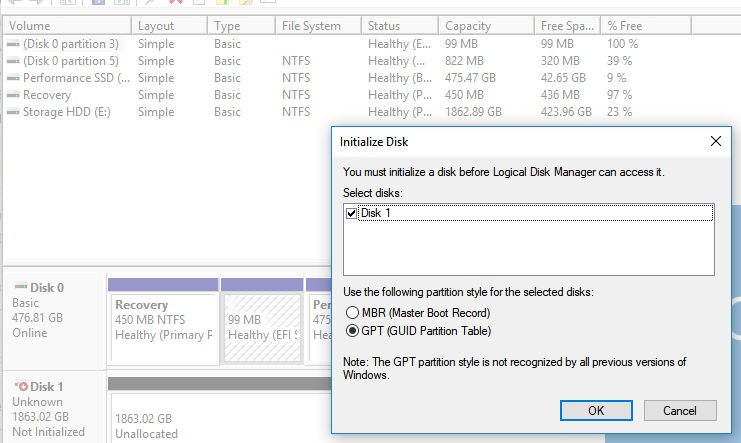
Initialise the drive with GPT Partition Style
GPT Partition Style
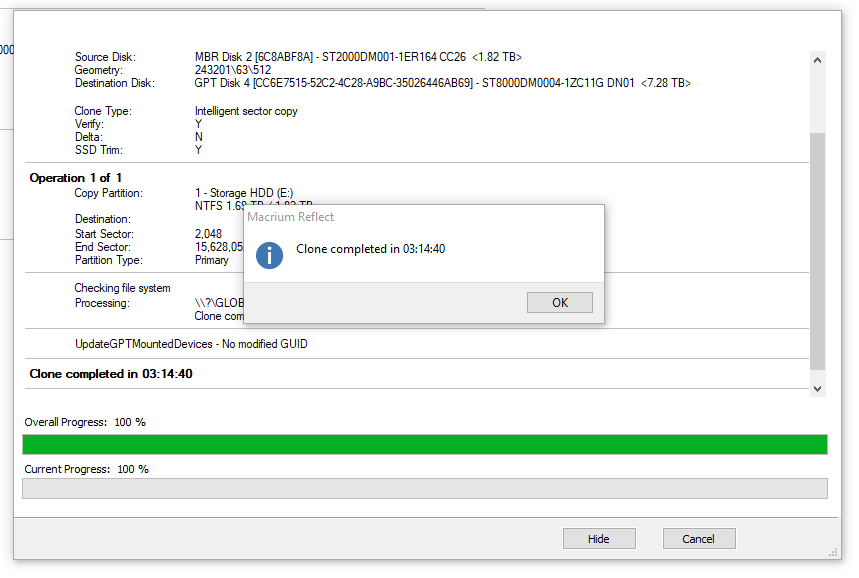
Use Macrium Reflect to clone the partition from the old drive – including all Box data – to the new drive
Cloning with Macrium Reflect
Reboot into Safe Mode
Use the video below to ‘swap the drive letters’. This step basically tricks Windows into using the new, larger hard drive (as the ‘E’ drive in my case). And Box Sync works perfectly, it just picks up where it left off.
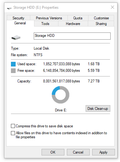
Now we have lots of room for Box Sync and more:
New hard drive capacity
One final thing I had to do was “uncompress” the drive data. I had used NTFS compression with the previous drive but now I no longer needed the compression. Just go to the file or folder properties and untick “Compress this drive”.
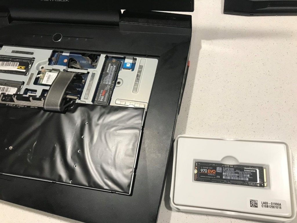
Adding a New SSD into My Metabox Laptop
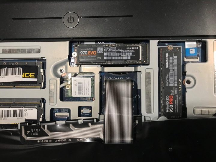
The next thing I did was add another SSD to my laptop. I looked up the manual and it said I had another M.2 2280 (22mm x 80mm) slot available. In the first slot I already had a Samsung 950 Pro 512gb as my primary drive. I did some research and decided to go with a Samsung EVO 970 2tb drive. After waiting patiently for my ebay order to arrive, I then cracked open the Metabox to install it.
Here is what I did:
Removed the back cover of the laptop
This is under the back cover of the Metabox
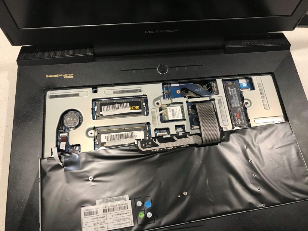
Looked around everywhere and couldn’t find the M.2 slot – in fact I couldn’t find my primary drive. After a moment of panic, and then a quick look on YouTube, I realised I had to remove my keyboard. So I removed the KB screw and carefully pried the keyboard off, then there it was – my spare M.2 slot!
Additional M.2 slot under the keyboard
New drive ready to install
I carefully installed the 2tb SSD and then closed up the laptop Installed
The system booted up fine, then I went into Disk Management and initialised the disk with a GPT record,
Created a new partition with NTFS default sector size, and
We are good to go!
Now that I had a much bigger SSD to work with, I immediately moved my Revizto Working Folder onto that new 2tb SSD. This will allow me to fully utilise a lot of the great new Revizto Point Cloud features and at the same time have full M.2 SSD performance.
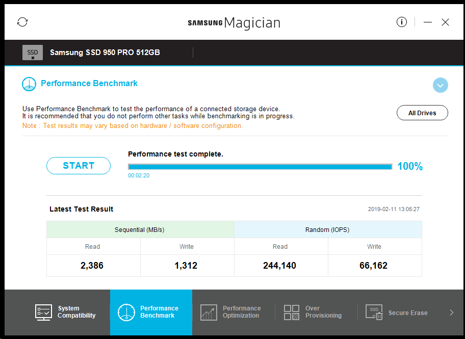
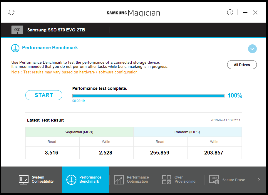
Update:
Out of interest, I have added the Samsung Magician performance scores for the Samsung SSD 950 PRO 512GB and Samsung SSD 970 EVO 2TB below:
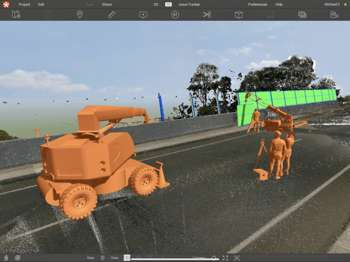
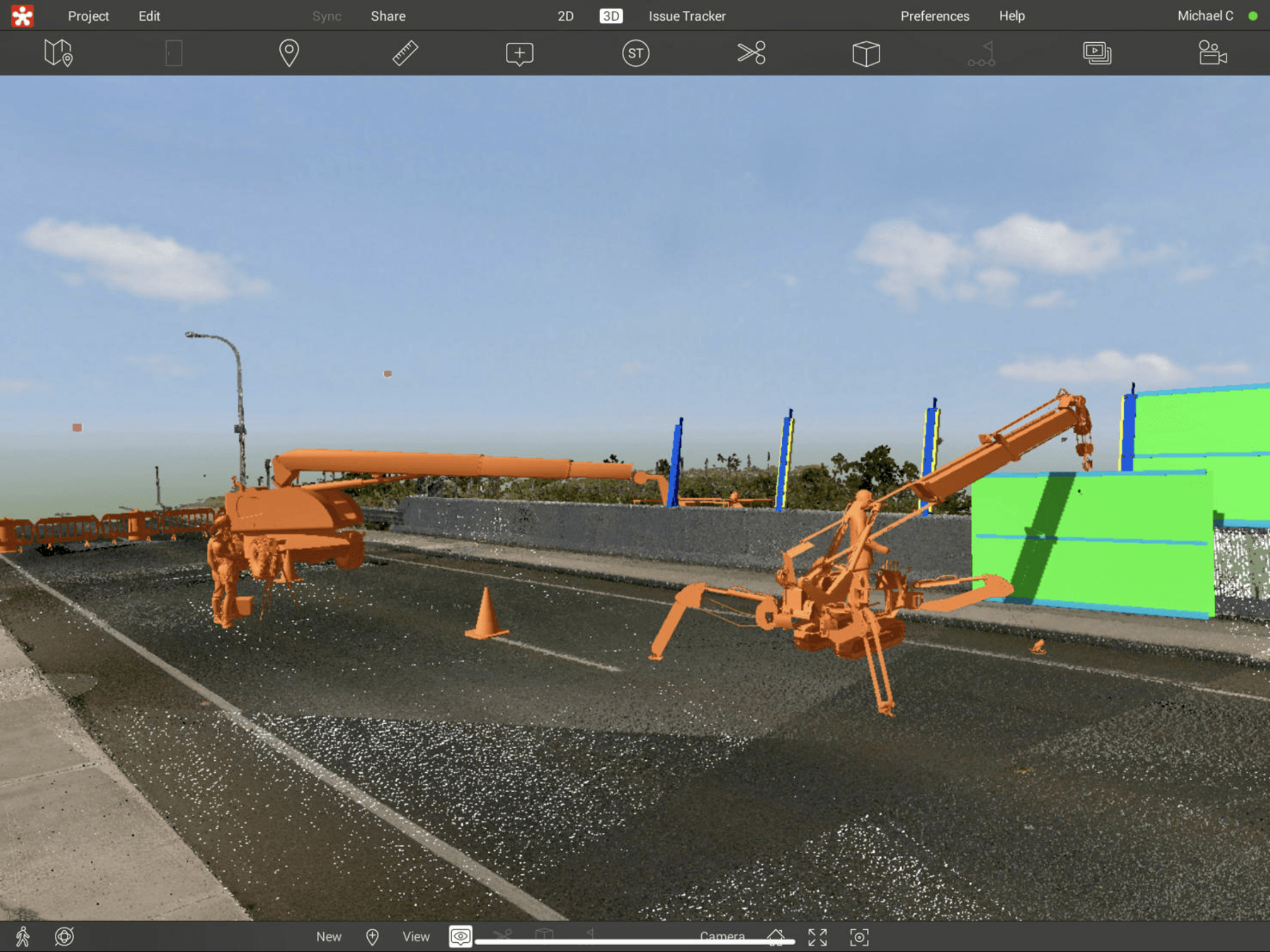
A brief look at what went on behind the scenes to create the visualisation of the Bridge Anti-throw screens. Checkout Revizto at https://revizto.com/en/
You have received a bunch of DWG files transmitted to you, and you want to quickly convert to a DWF, DWFx, or PDF file for downstream use (perhaps to import to Revizto).
Here is one way, assuming that layouts are uninitialized:
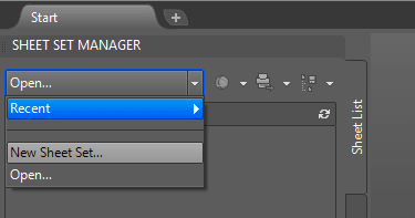
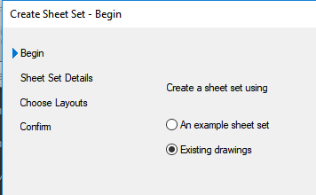
Open AutoCAD
New Sheet Set
Existing Drawings
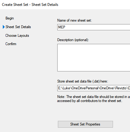
Give it a name and a home
Browse for sheets and insert them
Open 1 sheet
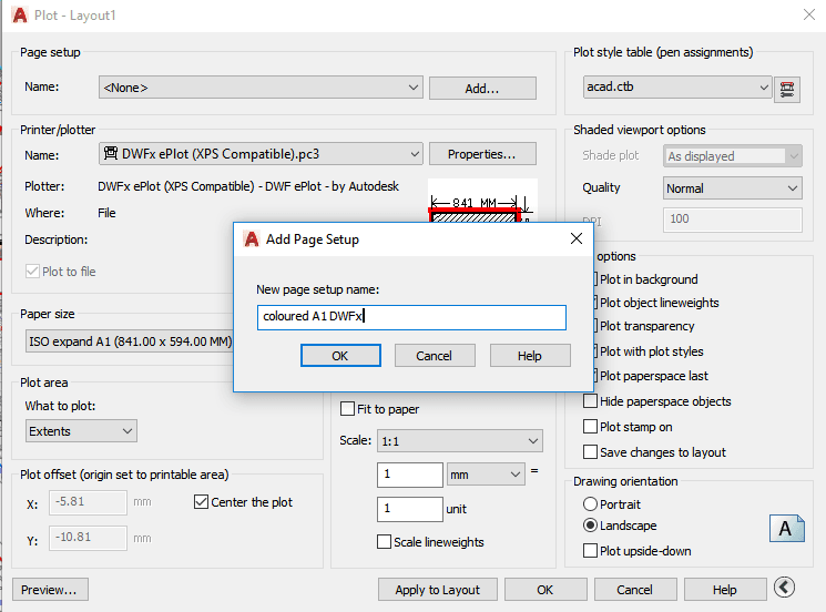
Create a page setup
Close and Save the DWG
—–
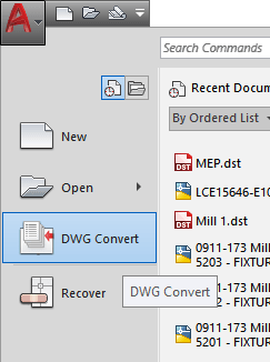
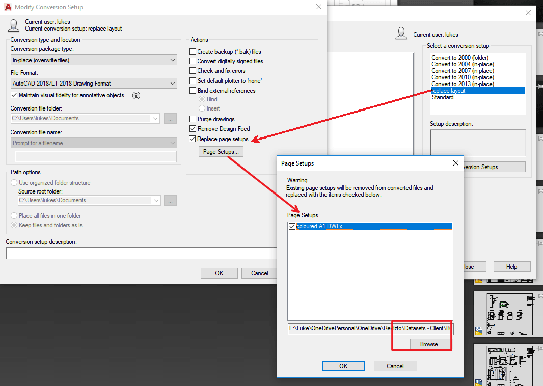
Optionally – Use the DWG Convert tool to ‘replace page setups’ to all sheets. If you don’t do this, you will have to use an Override / Imported Page Setup later in the process.
Type DWGCONVERT and hit Enter, or use Menu
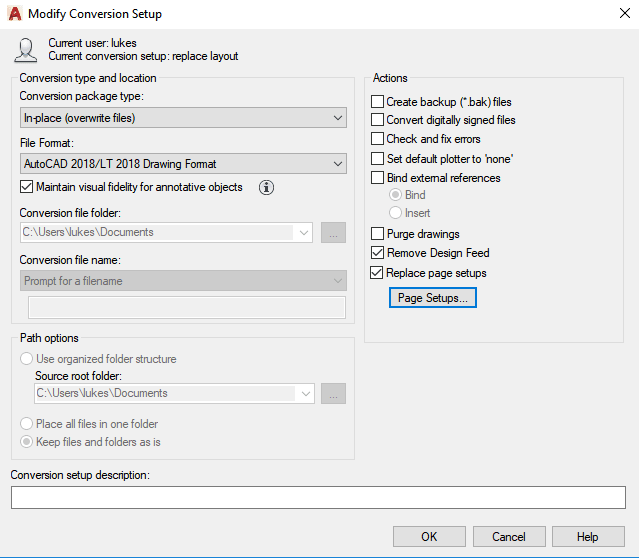
Create a new Conversion Setup
Click ‘Replace page setups’, and load the page setup from the file you created earlier.
Choose other options like “In-place (overwrite files)” and pick same version as those files currently are.
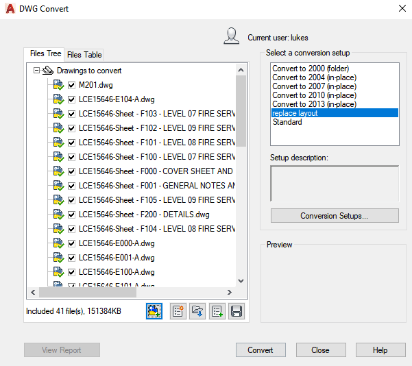
Add files to the Files Tree, then click Convert
—–
Now, you can use the embedded page setup in the Publish Dialog
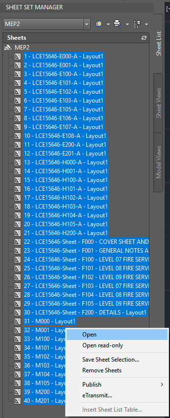
First, open all sheets in the AutoCAD session
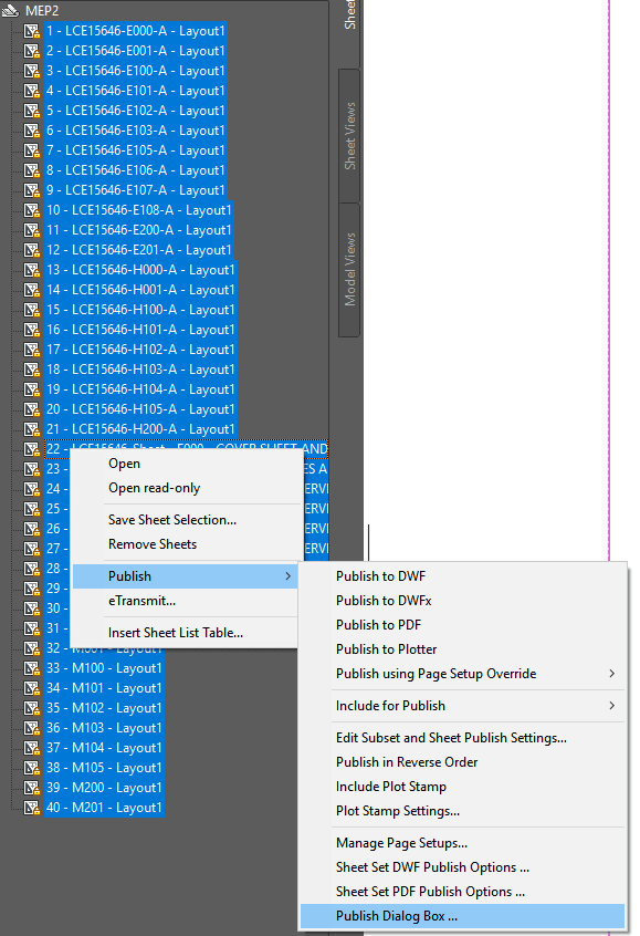
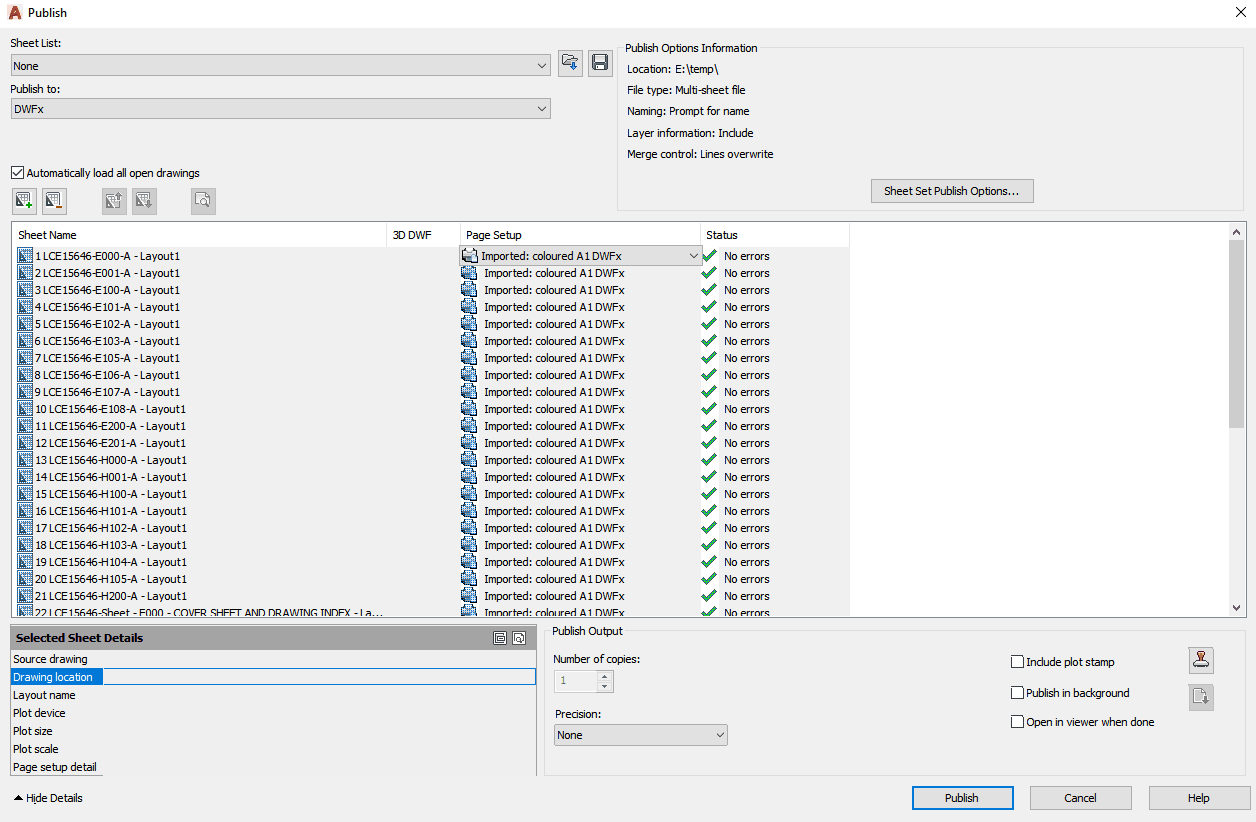
Once opened, go to Publish – Publish Dialog Box …
Choose Publish to: DWFx
Choose All Sheets
Change the Page Setup to the one you created earlier (at this point, you can optionally ‘Import’ the Page Setup if it doesn’t exist in those models)
Click Publish, and give the DWFx a name
You can now use this combined DWFx downstream (for example, you could import to Revizto and overlay to a 3D model).
You could use a similar method to batch convert DWG to DWF, or DWG to PDF.
A couple of days ago I was considering how Architects design, and how their processes can be very detailed and effective, and yet those ideas are often presented in somewhat traditional ways: like a binder full of prototypes and design ideas that lead to the ultimate solution of a specific design challenge. During this particular introspection, I came up with the term “Digital Prototyping Framework”. Let’s call it DPF, because what we need are more acronyms in the AEC industry.
In all seriousness, I believe I have come up with a term that describes a new era in collaborative and cloud based design platforms. The term “digital prototyping” already exists, it refers a way of doing things that gives conceptual design, engineering, manufacturing, and sales and marketing departments the ability to virtually explore a complete product before it’s built.Industrial designers, manufacturers, and engineers use Digital Prototyping to design , iterate, optimize, validate, and visualize their products digitally throughout the product development process.
The concept of frameworks in software design is also well known, referring to something that provides a standard way to build and deploy applications. A software framework is a universal, reusablesoftware environmentthat provides particular functionality…
By combining the idea of Digital Prototyping with Frameworks, I’m describing a tool or set of tools that empowers you to design, iterate, optimize, validate, and visualize in a standard environmentthat provides particular functionality.
The best example of a Digital Prototyping Framework that I’m aware of at the moment is Revizto. It provides a standard and consistent environment where design and feasibility studies may be recorded, discussed and reviewed. It combines 2D and 3D context, along with other technologies that provide high-value context to design tasks. It allows direct integration with reality capture and meshed photogrammetry, along with the ability to attach other data types to design nodes (referred to as “issues”).
Digital Prototyping Frameworks facilitate knowledge sharing and distributed design efforts, as the design process is fully exposed and transparent to those invited to the framework. The environment becomes familiar, and interactions are increasingly focused on design and ideation, rather than becoming distracted by technological barriers to design.
What is a Digital Prototyping Framework?
A tool or set of tools that empowers you to design, iterate, optimize, validate, and visualize in a standard environmentthat provides particular functionality, while providing access to contextual and historical data.
Why did I invent this term?
I hate the term “digital twin”. I think it is simplistic and does not describe anything useful about underlying processes and workflows. It implies “identicalness” between the physical and digital world, which is a grossly juvenile comprehension of potentially deep and complicated differences between something that is physically real and something that is not.
I believe we need some new terminology to describe new ways of working. BIM and VDC are some of these terms, but a DPF is part of how we connect BIM with VDC.
An example of a DPF in use:
Michael Clothier from Virtual Built Technology worked with Bronte Modra from Specialised Solutions to prototype and visualise the work required to install “anti throw” screens on a bridge in our local area. They combined reality capture information with physical models in the Revizto collaborative visualisation environment, and it was used as a DPF to describe both the design and the installation process.