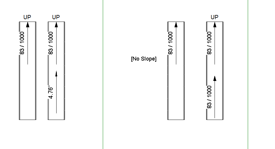
In Revit 2013, you can’t tag the slope of ramps in Plan views using the Spot Slope tool.  There are workarounds out there already, but here is an easy one:

  1. Make a new Generic Model Adaptive family with 2 Placement Points
  2. Make a spline between these two points (select them and then hit the spline by points button).  Set its category to Invisible
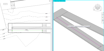
  3. Load this Family into a Project, and using a 3D view, place it at the centre line of a ramp (the two points should snap to the correct location in 3D)
  4. In a Plan view, use the standard Spot Slope tool in Revit – just pick the adaptive component “line” that you just placed.

EDIT 
As I mentioned above, there are other workarounds for this. One is to put a slope arrow on an adjacent Floor, then copy it on top of a Ramp. It works!

Check out comments and video link below…

Link:
http://www.youtube.com/watch?feature=player_detailpage&v=IJD14dDUKbU#t=71s

I actually found this did not work too well in Revit 2013 (no problem in 2012).  However, after a bit of fiddling, I have created 3 files (one for Revit 2012, 2013 and 2014) – all of which have spot slopes on Ramps that can be copied around.  Here is the link:
View / download


Remember Julien Benoit’s adaptive component tutorial from a year ago (link here)?  Well, Julien has made something pretty cool and posted it on RFO.  It is basically a 4 point adaptive component that calculates the area of the resulting surface using Bretschneider’s formula.

Julien’s solution (using an intense formula):
File Type: rfa AreaTool#2013_AC_CP_4P.rfa 208.0 KB

This is the formula, if you are interested (!)
sqrt((P – A) * (P – B) * (P – C) * (P – D) – ((A * B * C * D) * cos((BB + CC) / 2) ^ 2))

Alfredo’s more volumetric solution:
File Type: rvt Project_panel_areas.rvt 960.0 KB

Note: you will have to login to RFO to download from these links.

Read the whole thread:
AC curtain panel as measurement tool

Point clouds are getting a lot of “press” lately, and they can be very useful.  But let’s say, hypothetically, that you have a 3D model of a building or a component and you want to deconstruct it back into a point cloud –  Can this be done?  Yes, and quite easily…

  1. Open the 3D model in 3dsMax
  2. Export to STL
  3. Import the STL into MeshLab (File – Import Mesh)
  4. Export the mesh as an XYZ file (File – Export Mesh As…)
  5. This XYZ file can now be imported into Recap, or indexed by Revit into a PCG, or used in various other software tools

Note:  You can also create STL files (steps 1 and 2) directly from Revit using the STL Exporter add-in.

Some of these tools were discussed at:
Free 3D PDF from Revit STL using Meshlab, MiKTeX and U3D-2-PDF

I received this request via email:
a question in revit vasari or you can get the orientation and exposure of a face of a mass or a wall
for example
classify all the walls to the north or the south-west?
and
put them in a schedule of the walls?

Vanilla Revit can’t do this. But perhaps someone would like to make a little add-in, macro or script that processes Walls, determines their ‘facing’ orientation, and then inputs this data into a Shared Parameter of Walls? Successful challenger will obviously get a mention on the blog.

Maybe something like this already exists out there… Feel free to comment!

ANSWER
Thanks to Amy Manning, who ‘reminded’ me that Case do have a tool that does exactly that 🙂

Its the aptly named “External Wall Facings”.  More info at this link.

Much of the legwork was done back in this 2010 post by Jeremy:
The Building Coder: South Facing Walls

Note:  I used my Revit Master Search, which led me to this post, which led me to Sort and Mark by tools4revit.  However, I don’t think this adds orientation relative to North – I’m pretty sure it just determines Flip/Mirror orentation?

Jeremy shows how you can review a DWG file to determine if the source entities were Text or Labels in Revit.  This principle extends further, as he describes:

The differing TypedValue 11 is consistently -2000300 for a text and -2000280 for a label element.
What does this mean?
Well, is actually quite easy.
On seeing these large negative numbers in this specific range, an experienced Revit developer will quickly suspect built-in category or parameter enumeration values.
You can check what they actually represent in the Visual Studio debugger, by jumping to the definition of these enumerations and searching for the specific values.
Looking back at an ancient blog post on the DWG and DXF export Xdata specification confirms that these numbers do indeed represent the built-in category of the source element and thus can be used to distinguish the two.

via
The Building Coder: DWG Issues and Various Other Updates

Update Release 1 is not a full install; rather it is using service pack technology similar to AutoCAD®- based products. Prior to installing the Update Release 1, please verify that you have already installed the First Customer Ship build of Autodesk Inventor 2014.
You can apply this update to Autodesk Inventor 2014 running on all supported operating systems and languages. Consult the readme file for installation instructions and be sure to install the correct update (32-bit or 64-bit) for your software and operating system.  This Update Release improves data integrity and visual fidelity when exchanging models with Revit.

Readme (select language version):

English (htm – 29Kb)

via
Autodesk – Autodesk Inventor Services & Support – Revit Interoperability for Inventor 2014 – Update Release 1