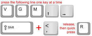
Follow these steps:

That should get you to the Room Separation line entry in Visibility / Graphics.  Then, you can:

  • press Spacebar to toggle visibility on / off
  • press Right Arrow, then Spacebar to open the Override sub-dialog

As you probably know, I’m a big believer in Keyboard Shortcuts.

However, in all honesty, if you have mouse and are using Revit 2013, it is probably going to be quicker to:

  • Select a Room Separation line
  • Right-click
  • Override Graphics in View – By Category…
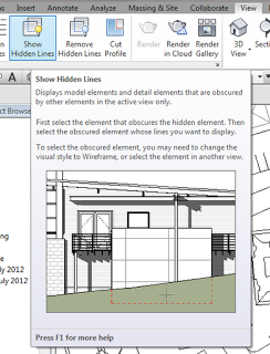
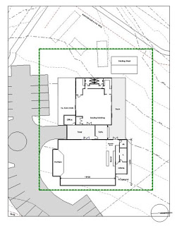
I have been using Revit for over 5 years now, and I don’t think I have ever used the Show Hidden Lines tool.  Am I the only one?  Basically, its a two pick tool, first pick for the ‘front’ element, second pick for the ‘back’ one – then, then lines from the back element will show through as Hidden Lines.

This tool is hiding on the View ribbon panel:

From the Wiki:
After you put detail components in the correct graphic draw order, you can use the Show Hidden Lines tool to obscure the lines behind a detail component.
via
Show Hidden Lines – WikiHelp

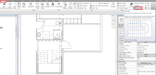
Pre-2013 sketch based stairs have the Stair Path bound to the actual Stair element.  In Revit 2013 when using Component Stairs, the Stair Path becomes a separate element.  Think of it as a special Tag for Stairs.  The Stair Path tool is located on the Annotate ribbon:

You can safely delete the path from views where you don’t want to see it.  It seems that these are automatically created in certain Plan views – I’m unsure what the ‘rule’ governing the automatic creation of Stair Paths is, yet.

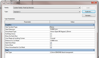
The Stair Path is a System Family.  You can Duplicate existing Path types to create and customize the Stair Path to your liking:

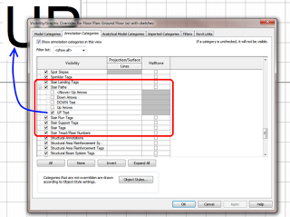
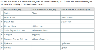
Also, the Categories related to Stair UP and DOWN text have all been moved to the Annotation Categories in Visibility / Graphics!  You won’t find them under Model – Stairs anymore:

You can learn more at:
Annotating the Stair Path – WikiHelp

Awesome post to Wikihelp by Ping Jiang, Software Quality Assurance Engineer, Autodesk.

The short version:
basically when the old stairs upgrade to Revit 2013 and mix with new stairs in the project, we just need to simply uncheck the visibility of ‘above’Riser Lines and Riser Lines, then the representation for them will be almost exactly the same [as pre-2013] in all the views.

Read the complete and detailed guide at:
Stairs Representation During Upgrade – WikiHelp

In Revit 2012, right-click Override Category in View put you into the VG dialog, and you had to scroll to find what you were after – annoying!  Revit 2013 is heaps better – it simply provides a dialog similar to that used for Override Element in View.  This allows for a much improved workflow.  See the 25 second video below:

This is kinda weird.  I opened this 2012 family in 2013 – and now when I turn things on and off in the Family Editor, they completely disappear (they don’t just gray out as you would expect). 

It is a scary little line based Casework family that I made a while back.  It has heaps of instance parameter dimensions and is a generally a bit of a nightmare – but still, why is this strange issue occurring?  Any ideas?

Watch the video below, and download the family here.

In Revit, you can’t use the linework tool on the physical edge of a Toposurface.  Worse still, the edge has no distinct category of its own.

The only viable workaround that lets you consistently hide the edge of a Toposurface is to change its Object Style color to white.  You can still set you Primary and Secondary contours to show in black or whatever color you use.

This method creates its own problems – like if you draw a grey filled region over the edge of the Toposurface, the ‘white’ line may show through and print.  In any case, feel free to ask Autodesk for some better visibility control over Toposurface elements.

While you are at it, why not ask for Toposurfaces to comprehend phasing properly?

Tip via:
AUGI – View Single Post – Linework tool w/ Topography

There are at least two ways to work around the fact that a Plan Region will not affect the viewing of Topography elements.  From the AUGI forums (2007):
Alex Page
What about having a ‘cut-plane’ of the view above the topography and doing a plan region around your house? (ie: reverse the logic)

Steve_Stafford
You could try creating a view of the toposurface from a higher vantage point that doesn’t include showing the building. Then overlay this view with the view of the building (overlay on a sheet that is) at the level you want without the toposurface. This way the two views give you the whole but permit the two different cut planes you really need. If you set the toposurface view to wireframe it should give you the look you want, guessing what that really is, though.

via
Plan regions have no effect on Topography?? [Archive] – AUGI

I have used a similar technique for residential housing – where you can have repetitive plans with only small differences. It can even be adapted to work in a demolition scenario.

The visibility in each applicable view must be set appropriately, but the net result is cleaner and easier to control than the other methods.

Thanks to Aaron Maller for the video.