Under-slab insulation (fitted or fixed below a concrete slab) is a legitimate coordination item. Typically it is installed first on site, so other trades and services must fit in around it.

This means it needs to be modelled by someone, which can be a headache in Revit. The slab soffit (underside of slab) often moves up and with concrete beams and pads. If you have access to editing the structural model, you may look for a way to incorporate slab insulation into the floor items themselves. However, this still does not work well for the vertical faces of a slab setdown.

To solve these, I created two families:

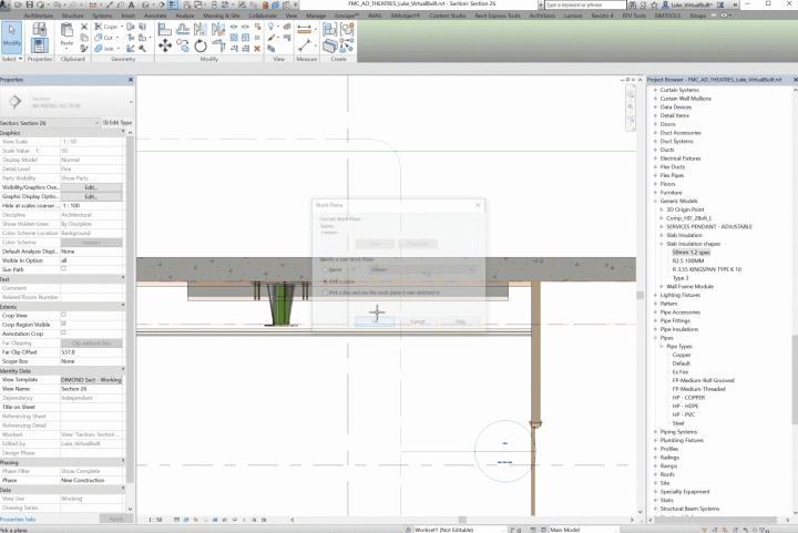
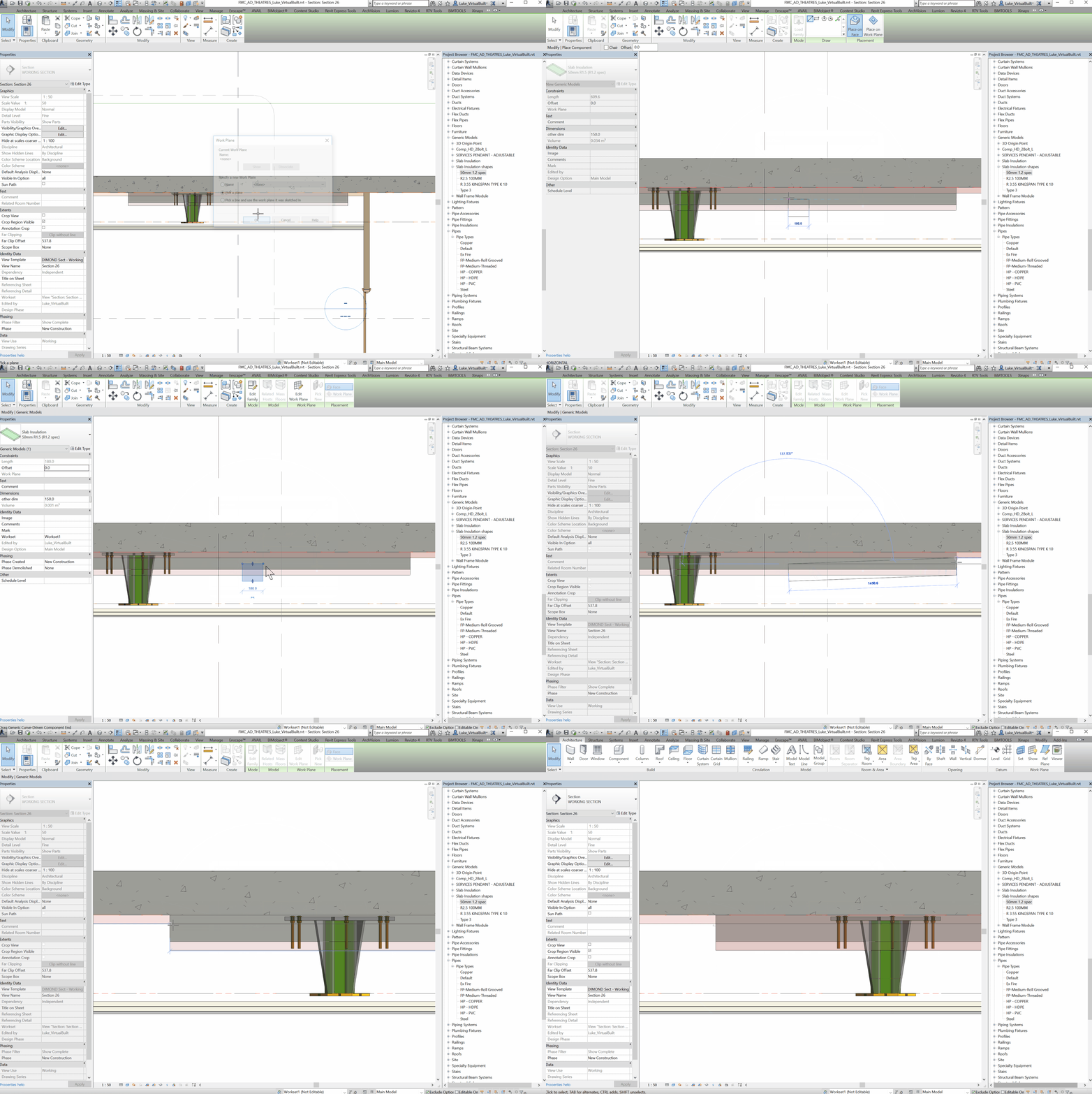
  1. A line-based, face-based Generic Model family that can be simply placed and stretched
  2. A 4-point adaptive component for irregular shapes. After placement, the four corners can be selected and moved into place.

You can download them here:

Slab Insulation shapes

And this gif shows the rectangular version in action:

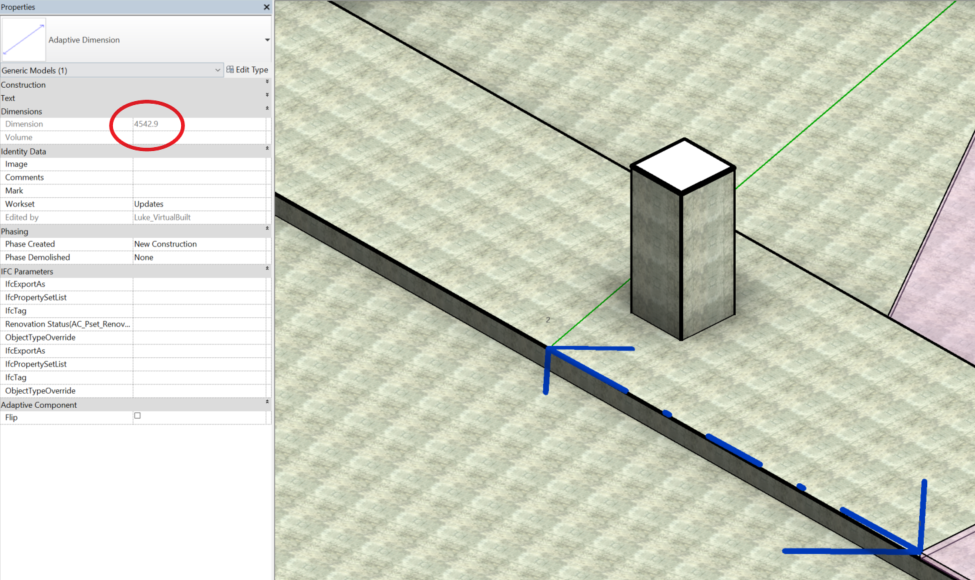
When working in 3D in Revit, you *can* use the normal dimension tool *if* you first set the Workplane. However, this can get annoying. Why not make a 2 point adaptive family, with a reporting parameter, so that you can just place the family (two clicks) and then check the instance parameter as shown below?

Update: V2 with arrowhead and tag in project Download here

Adaptive dimension family (2016), Download here


Revit wants you to make your own better, faster way sometimes…

Jeremy Roh has created some decent tutorial content and shared it on Youtube, covering topics such as Revit, conceptual modelling and Dynamo. One of his recent playlists is embedded here:

Check out his channel for more at:
Jeremy Roh – YouTube

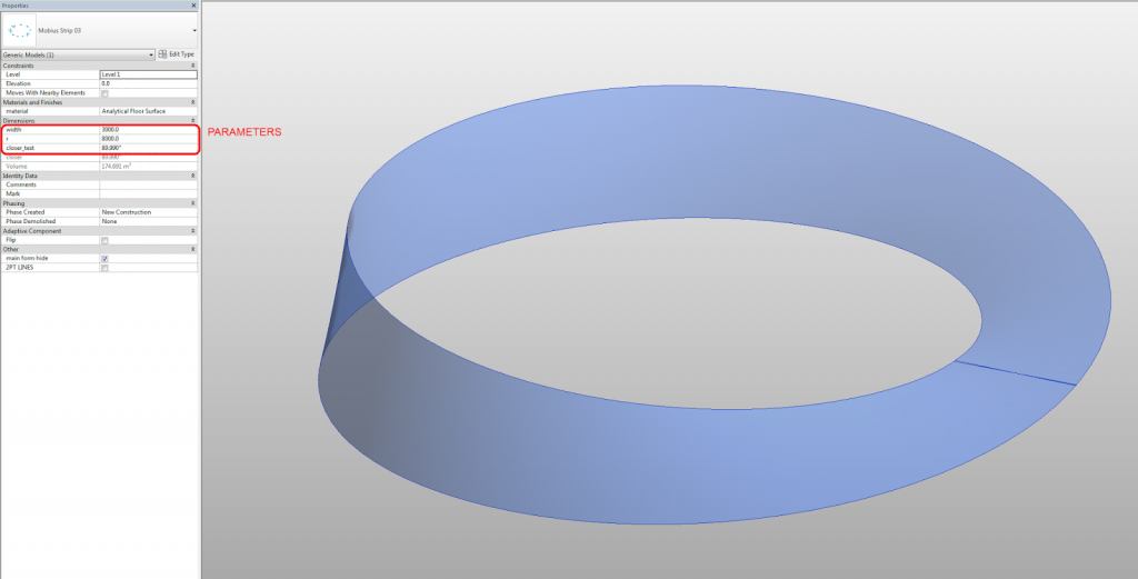
Over the years, there have been a few attempts at modelling a Mobius Strip (or band) in Revit.  The BIM Troublemaker had a go back in 2010, Chad also tried in the comments, and The Proving Ground showed a method with RevitPythonShell.  Another guy tried using a massive rig on Youtube (skip to 7.55).

For me, the conceptual analysis of this problem goes back to a fundamental question – is a piece of paper a surface, or a solid?  It is really both, depending on the accuracy of the equipment you are using to measure thickness.  When it comes to modelling it in Revit, I prefer to think of it as a surface – something with no inherent thickness, just a piece of stuff that we twist 180 degrees and try to stick back to itself.

Similarly, I’m more concerned with making the Mobius Strip out of one piece (one “Create Form”), rather than two pieces.  And I’m not too worried about seeing a single seam line – even the piece of paper Mobius Band has visible sticky tape 🙂

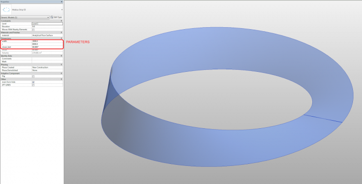
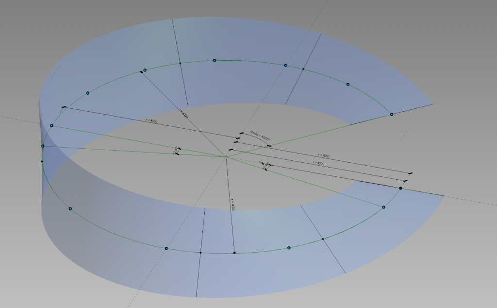
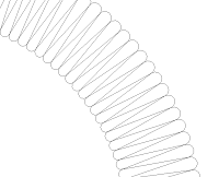
So in my example, I created a form derived from nested line families (parametric band width) that are hosted on Reference Points.  These Reference Points are driven by the Normalized Curve Parameter and Rotation Angle to set up a slowly twisting rig for the Create Form.  The Reference Points live on a Spline, that was placed on a Divided Path based on Arc / Circle segments.  This gives me two things – a simulated rig-driven “circle” that is actually a Spline (that has a parametric radius), and the ability to add a “Closer” parameter to push the two ends of the band together.

Hey, I know its not perfect, but it was a bit of fun!  Oh, and did I mention that the Wall by Face tool in Revit will happily generate a wall from this family in a single click?

You can download the example here:
https://drive.google.com/file/d/0B1dGdRkpk2beZ0FaMDIxai15aUE/edit?usp=sharing
I have posted about Profiles and Adaptive components before, but more recently Tim Waldock put together a nice, detailed post on the subject over at this link.

In the post, he states:
You can host it on a divided path node; but don’t bother to convert it to a repeater because it cannot then be used to create a solid form.

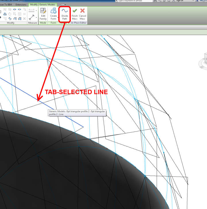
Technically, this is true.  If the element is not a Repeater – just a set of Profiles in an Adaptive, you can then Tab-select until you get the “closed” loop of lines, and use these to generate forms.  In other words, you aren’t selecting the Component – just the lines inside the component.  It can be a little fiddly, but it does work.  This is only really necessary if the normal workflow of selecting the Components and using Create Form does not work or is not available.

However, when it comes to Repeaters, even the above idea does not work.

Neither does “doubly nesting” another shared Component inside the Repeated Component.

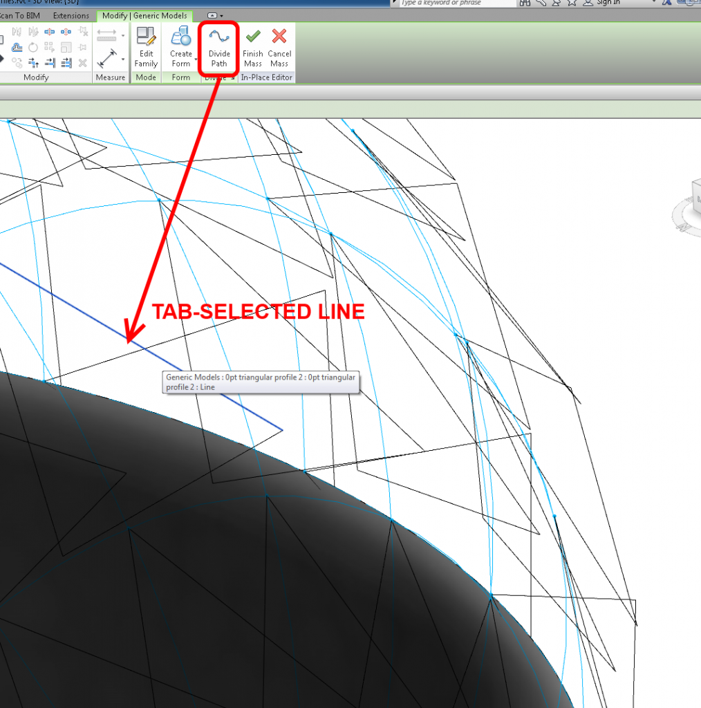
One of the few things you can do is to select a Line in the Repeated Component and use the Divide tool.

You are then left with using the Repeater to set up a “rig” to place multi-point line families on or between, and using this skeleton to generate forms.  In some ways, it depends how parametric and adjustable you need the resulting form to be…

Have you ever wanted to rationalise your Topography as a Massing form, perhaps so you could use Divided Surface and panelization tools on the topo?

Here is one method:
  1. Make a Site family with a vertical model line and height parameter (see sample file at end of post)
  2. New Project – Make a Toposurface (or existing project with Topo)
  3. New in-place Mass
  4. Place the Site family on the Topo in one corner – it will detect the Topo and host itself to it, even though you are in the Massing environment
  5. Copy a certain number of times in X direction.  Basically, you are forming one part of a grid sampler…
  6. Make a new Adaptive with the same number of points as step above.  I made a 20 point adaptive.
  7. Select all the points, make sure they are Adaptive, Spline through Points
  8. You now have a 20pt Model Line spline… Load into Project
  9. In Massing environment, place the 20pt component by clicking on the very top of the vertical Model Lines from the Site family (as you place it, the points will change to a smaller point size to show it is “living” on the top of that line)
  10. Now, select the whole row of Site families and the 20pt component and copy it along the other planar axis (this is the other part of the sample grid mentioned in step 5)
  11. As the elements are copied, the Site families will host themselves to the Topography, and the Spline will adjust accordingly
  12. Now, select all of the spline families and Create Form!
  13. You can adjust how close to the original site the Massing form is by using the height parameter of the Site model line family
This method could be used in conjunction with the Tree randomizer here.
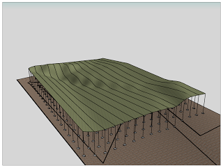
The image shows the sample surface above, and the original Toposurface below.
The only limitation I found was that if the form is “flat” at some point, the Create Form may not work.  However, if each Spline does vary up and down, it should work ok.

HyunWoo Kim has been posting some very interesting stuff over the last couple to his English-language blog, Enjoy Revit.  The content of his blog is quite interesting to me – including adaptive component rigs, solving documentation problems, and dealing with family and content creation issues.

2 point and 3 point Circle Adaptive rigs
with formulas, and this arch family for download

Symbol Annotation as 3pt Adaptive for sections
download

A very curved automatic Adaptive Stair
download

Workaround to enable the “Show Only if Instance is Cut” option for Symbolic lines
(ie. switch to Structural Framing and back again)

Curved Insulation Family
download (quite a lot of work in this)

The hidden edge trick in 3dsMax for Sketchup import to Revit
I posted about this here

His Korean site is at Enjoy Revit : 네이버 블로그 .  He also has a Google Site at:
Enjoy Revit.

He is quite prolific on Youtube too – his channel (in English) is:
HyunWoo Kim – YouTube