Links for Revit 2015 UR9 for R2:
Download link
Readme
Enhancements List
Download link for Revit 2015 UR9 not for R2:
Download link
Enhancements List (plain text):
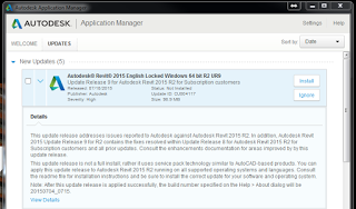
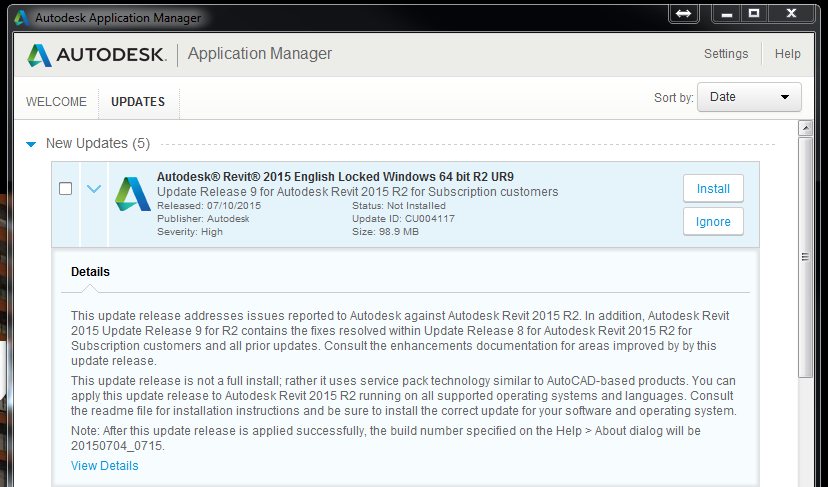
Improvements made in Update Release 9
Revit 2015 build: 20150702_1515
Revit 2015 R2 build: 20150704_0715
Autodesk® Revit® Platform 2015 Updates
Improves stability when deleting an element which contained an invalid partition ID.*
Improves visual fidelity when exporting to DWF.*
Improves data consistency between a schedule view and a schedule instance on a sheet.*
Improves stability while upgrading Revit 2012 projects.*
Improves stability while editing families.*
Improves stability when using the Options dialog to log into A360 from a workshared central file.*
Autodesk® Revit® MEP 2015 Updates
Improves stability when upgrading a project that contains user-created pipe types.*
Autodesk® Revit® Structure 2015 Updates
Improves stability while when placing a slanted column or a beam based on a Generic Model Line based family.*
Improves stability when reloading an annotation symbol family used as a symbolic representation of brace elements on plan views.*
Autodesk® Revit® API 2015 Updates
Improves stability while when editing families which use external resources for keynotes.*