Not a great position to be in (having point clouds with different coordinate systems and no known common point), but here is some code that may help:
andymiller/FeatureBasedAlignment · GitHub

From GibHub:
The goal is to accurately register two point clouds created from different image spectrums (e.g. visual to infrared), in different coordinate systems of different scales.

Current approach is: 
– Take two point clouds 
 – Estimate normals for each point 
– Find FPFH Features for each point 
– Find likely correspondences between two models (based on FPFH) 
– Use top features to estimate scale, 
 – Run RANSAC to estimate transformation, and eliminate correspondences 
– Use remaining correspondences to run ICP for finer alignment

In the Shared Parameter .txt file (the one in use in your office or project, as per Revit parameter settings), there is a visibility switch at the end of the line for each parameter.

Set it as follows:
1 for visible
0 for invisible

Make sure you don’t load this parameter into Family or Project until after you have set the desired parameter to 0 for invisible and saved the text file.

In other words:

  1. Create the new SP
  2. Edit the text file and change the switch to 0
  3. Add the Parameter to the applicable Family, Project or both

These hidden SPs can still be scheduled and tagged in the Project, you just can’t “see” the parameter entry.

This method could be useful for simplifying the presentation or “interface” of families, or perhaps even for concealing calculations and formulas that never require user input.

If Cleartype is not really working for you (perhaps you are having compatibility issues with Google Chrome and Windows XP 64 bit), then you could try replacing the font renderer with free MacType.

Download from here:
MacTypeInstaller_2012_1022_0.exe – mactype – MacType 1.2012.1022.0 – Ultimate font Rasterizer for Windows – Google Project Hosting

It has lots of different modes and options – but you can use it to selectively replace the font renderer for a single process in “standalone loading” mode.

The result is quite impressive…

Just had a great meeting with Andy Parnell-Hopkinson of 3Dconnexion GmbH.

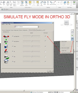
In the course of our discussion, Andy solved a problem that had bothered me with the SPP – how to use Fly mode in a 3D orthographic view (the option is greyed out).  The solution is so easy, just reverse a few axis:

By reversing these axis, the Fly mode is basically simulated – instead of moving the objects toward you when pulling back on the SPP, it pushes them away etc.

As you know, 3D orthographic views are probably the most useful view for modelling in Revit, so this tip should make some of you very happy 🙂

Then you can download Autodesk Inventor View 2014.

Share native Autodesk® Inventor® software data with non-Autodesk Inventor users with this freely distributable viewer that delivers high-fidelity viewing and printing of parts, assemblies and drawings.

Important: Ensure you download and install the version of Inventor View 2014 appropriate for your operating system. Additionally, you should not install this software on a computer that already has Autodesk Inventor 2014 software installed.

Autodesk Inventor View 2014 (32bit) (exe – 672610Kb)

Autodesk Inventor View 2014 (64bit) (exe – 774802Kb)

Readme (htm – 24Kb) 

via Autodesk – Autodesk Inventor View 2014

Following this tweet from Sean:

(which was in response to my post about the Revit Category Guide.)

I was tempted to use the IFC roundtrip method to make some Road families in Revit.  So, here they are for download:

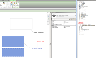
You can’t Schedule or Tag them normally, but you can use Material Tags, modify the Category and Subcategories using Object Styles, and view them in the Project Browser.

As always, use these “unsupported” methods with care…

Here are some similar posts:
Convert All Masses (including in-place Mass) to Generic Models via IFC

You can break Revit by making Room families

In-place and Component families of Stair and Railing Category

Interesting new addition to the Labs site.  I think it is intended for Factory workflows, but theoretically could be adapted for BIM productivity analysis.  You basically define Sources, Processors and Buffers to visually analyse the flow of “stuff” through the Process.

In BIM terms, I’m thinking you could visualise “Sources” of content creators into a BIM buffer, which then has outputs in terms of project milestones or deliverables.  Just an idea…

Download and try it out over at Autodesk Labs

What does it do?
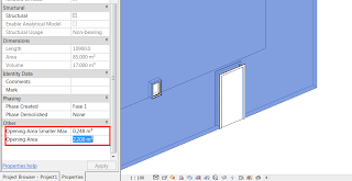
Gives you more granular control over the calculation of wall and opening area

The results you get are divided according to an area value you can set. All the openings below that Maximum value are stored as Opening Area Smaller Max, and the total openings area are added to the Opening Area Parameter. Now, you can schedule this parameters and get the Gross area of the wall by playing with calculated parameters.
Heads-up and more info from here

Where can you get it?
From here

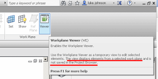
Have you ever used the Workplane Viewer?  It looks like this:

When you open it, a new window opens and orients itself to the current workplane.  This window is the Workplane Viewer.

Revit Wants you to be understand workplanes, and to host things on correct workplanes in the model.  Virtually the entire model in Revit is built up on a series of 2D planes.  Additionally, being comfortable working in 3D views is an important Revit and BIM skill.  This is why you should use the Workplane Viewer…

A few impressive things about the Workplane Viewer:

  • Can be put on a secondary monitor and it remains open
  • It respects the Section Box of the currently active 3D view
  • Auto zooms to the extent of proper sketch elements when in a Sketch Mode
  • Keeps itself oriented to the current and correct workplane
  • It reports the currently set workplane in text form in the bar at the top of the window
  • Triggering Zoom Extents will affect both the current view and the Workplane Viewer
Interestingly, if a horizontal workplane is set (which is typically the case) and you are working in 3D, the Workplane Viewer will be giving you a Top View of the current 3D view – quite useful really.
The extent to which you can edit elements in the Workplane Viewer is dependant on the mode you are currently in.  Sketch modes allow you to edit sketch lines in the Viewer.  Editing a Family In-place allows you to select and modify extrusions.
It is a bit strange that the Workplane Viewer itself actually allows you to Orbit and use the Viewcube (meaning that you are no longer perpendicular to the current workplane.)  To fix this, go to a normal view and use the Set Workplane tool – the Workplane Viewer should now be back in sync with the current workplane.
In some respects, it is like the Replicate Window command, but the Workplane Viewer has a bit more intelligence when it comes to planes, and it is allowed to live on a secondary monitor.
Link to help:
Editing with the Workplane Viewer – WikiHelp