You have a scanned image of a Contour Plan, and you want to convert that raster image into useful vector data.  How do you go about it?

In the past, I would have used vanilla AutoCAD to trace the contours to polylines, then I might ‘spline’ them, then convert back to polylines (using a LISP tool), set all the elevations properly, and then import to Revit, then Create from Import to make the Topography.  Fun!

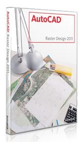
However, this week I have fallen in love with a new tool.  Its called AutoCAD Raster Design.  I’ll admit – it’s not perfect.  But it is smart, and it makes the process much more bearable.  Just follow these steps:

  1. Download the AutoCAD Raster Design trial from here
  2. You need vanilla AutoCAD installed already…
  3. Install AutoCAD Raster Design
  4. Scan your image using scanning software.  Save as pretty much any format, such as a JPG.
  5. Open Raster Design.
  6. Click ‘Insert Image…’
  7. Just do Quick Insert to get your image in quickly.
  8. Now use the Histogram tool from the Raster – Image Processing menu.  Try and get a lot of ‘contrast’ into your image.
  9. Use the ‘Change Color Depth’ tool from the Raster – Image Processing menu.  Reduce to Grayscale and then Bitonal.  You really need to get the image into a ‘Bitonal’ form to make use of the vectorization tools.
  10. Use the Despeckle tool from the Raster – Cleanup menu to get rid of little dots…
  11. Now that you have a nice clean Bitonal Image, go to the Raster – Vectorization tools menu and choose ‘Contour Follower’.  This tool is pretty self explanatory – just follow the command prompts and experiment with the options on the command line.
  12. You may need to tweak the ‘Options’ under the Raster menu – Options.  On the Raster Entity Detection tab, tweak these settings to suit your image.  Also under the VTools Follower tab, tweak these settings to suit your Elevation Interval…
  13. Finally, you will want to turn on Raster Snap under the Raster menu.  This will snap to the Bitonal image elements quite nicely.

Once you have traced all your contours and set proper elevations, save the DWG.  You will be prompted to also save the image…

Now import your DWG into Revit and use it to make your Topography.

Obviously, what Revit wants is for you to use accurate data at all times – so if you can get access to a proper DWG of the Contour Plan, do that!  In the meantime, you can use the abovementioned process to get the project under way…

raster-2975375

“It is the biggest project the firm has ever undertaken. There was very little planning with respect to file configuration; as a result, the project has now endured two model splits. We don’t want to do this again.”

(emphasis added)
From Huntington Beach, Here We Come

But isn’t that really at the heart of BIM? We push the limits, get beat up a little along the way, and then come out tougher than ever!

And…what Revit wants is for you to break up models that are huge.

As Revit users, we spend about 99% of our time behind a computer screen.  The brains of a computer are commonly known as a CPU (central processing unit).  These days, most CPUs have multiple cores.  The Core i7 975 that I use has 4 cores, and Hyperthreading means that Windows actually sees 8 cores.

Previously, I have discussed adjusting affinity and priority to make the best use of the cores you have.

If you are using an Intel chip, there is a high chance that it is using a technology called SpeedStep.  This basically ‘slows down’ your processor when its not busy.  I don’t know about you, but if I pay for a 3.33 ghz chip, I want it running at 3.33 ghz ALL THE TIME, not just when it thinks it has to…

To disable SpeedStep, head into your BIOS settings.  On the Gigabyte X58 I use, there is a section for ‘Advanced CPU Features’ and inside this, you can ‘turn off’ EIST (Enhanced Intel SpeedStep Technology).  There is also a similar feature known as ‘C1E‘ – I disabled this as well.

Now my processor is running at a consistent 3.33 ghz!

Here are a few tools and utilities you may find useful:

To disable SpeedStep WITHIN Windows while using a laptop with an appropriate Core processor, check out ThrottleStop.

To monitor CPU temperatures: CoreTemp

Benchmark and Torture Test: Prime95

Intel Processor Information Utility

Use all of these tools carefully.

corei7-7173705

If you have lots of materials in a project, it can become a chore to actually ‘choose’ them in the Material dialog box.

Here is a quicker way:

Scroll down for step by step version…

  1. In the Element or Type Properties box, select the Name of the material you want.
  2. Use Ctrl+C to copy the text.
  3. Go to the other Element or Type Properties box.
  4. In the appropriate material parameter location, select existing text with your cursor and then use Ctrl+V to paste the text.

This is a little plug for a new blog called Autodesk Explorer. Its still in its infancy, but if you are anything like me, you will want to add this to your extensive Revit blog reading list. There was a good tip on finding warning related objects in 3D wireframe mode:
Autodesk Explorer: Warnings, Warnings & More Warnings

If you would like to see a list of blogs I follow (with current posts), head over to:
Revit Professionals (aka Revit Blog Directory)


I found an interesting little PDF while using osun.org today.

It basically describes the features and benefits of Revit version 5.  Here is the link.

Here are a few gems:

Automatic sheet/drawing references
Ensures that no section, elevation, or callout ever references the wrong drawing or sheet.

Sketch-based hosts
Built-in-place items (wall, floor, roof, and so forth) are defined by simple 2D sketching, delivering flexible but geometrically complex 3D items in the building that can be iteratively changed by altering the sketch. 

And my favourite:
Align, split, trim, offset tools
These editing tools are like their CAD equivalents, but better. As you use these tools, they imply constraints between the things you pick so the model knows how to update as your design changes, saving effort and rework.

like their CAD equivalents, but better – what a way to sell it!

And some of the New Features in version 5:

“True North” views
View can be switched between Project North and True North orientation, saving time by eliminating the need to rotate text and symbols.

Temporary hide/show/isolate
Something getting in your way while editing? Now you can isolate your selection or temporarily hide it, reducing editing headaches.

It looks like Revit version 5 was released around December 2002.