Painfully, Architectural Walls in a Host model often occlude the Cut Pattern settings for Structural Columns in a Linked Model.  You may be able to see the edges of the Structural Columns, but any View overrides to the Revit Links tab, and even Filters, do not show the Structural Column cut pattern.

Essentially, the Walls in the host model are hiding them (like taking view order precedence or something).  Structural Columns should have Cut Dominance, but this does not seem to work where links are involved.

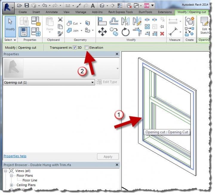
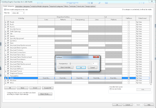
So, here is how to fix it – just override the Transparency of Walls to 1:

The Cut Pattern, including any overrides, instantly display:

Obviously, you can do this in a View Template for easy application to multiple views.

Helping search index:
structural column in revit link cut pattern

You need to save as PNG – but not any old PNG will work.

I have consistent success using Paint.NET, deleting the “background” so it is empty (checkerboard), then saving as a PNG.  But here’s the main lesson – make sure you tick 32-bit.  No other option seems to work, only 32-bit PNGs seem to respect transparency in Revit.

You can even use Bring to Front, Send to Back etc to overlap these images.  Quite useful for Entourage in coloured Plans and Elevations…

Daniel Stine hosted the interestingly named RTC class:
Mastering Materials: Getting What You Want from Revit

In a recent Cadalyst article, he gives a few good material tips.  Here are just 3 of them:

1) Material Assets
Think of a material as a container. Some of the information represents elements you can touch and see when the building is complete, while some does not. Assets are modules, if you will, that better define a material. These modules are optional and can be added or deleted as needed; however, most materials have an appearance asset, which cannot be deleted.

2) Material Transparency in Elevations (vs 3D views)
In any elevation view, materials are not transparent, as you can see in the left-hand image below (regardless of what Visual Style is set to). Even turning off the glass material in a view’s Visibility Graphics Overrides (VG) will not allow you to see through the “opening,” as seen in the second image. The trick here is to edit the opening in the family so it is transparent in elevation, as shown in the third image.

To achieve that, simply select the opening and check Elevation on the Options toolbar.

3) Self Illumination
 A surface with a self-illuminating material will actually add light to a scene. In the image below, the self-illuminating low wall in the center of the room is the only light source. This material can also be used to get a very white surface when nothing else seems to be working.

Read more / via
http://www.cadalyst.com/cad/revit/understanding-autodesk-revit-materials-17422

In Revit 2013, the Properties Palette does not expose the Graphic Display Options button in the Family Environment:

However, you can still get to the Graphic Display Options by using the View Control Bar:

This is handy, because it lets you use the nice Transparency slider while editing complex families or when tracing over Raster Images.

On a side note, if you ever want to know what each part of the User Interface in Revit is officially called, check out this link.

The Revit Kid demonstrated today that PNG files exported from a Revit render have no background.

In the spirit of one-up-man-ship, I recommend that you use TIF if you want to keep the background, but quickly separate it from the model elements.  When you export as TIF, you get a bonus Alpha channel that you can use to create a selection area and move the background to a new layer.

In simple terms:

  1. Export Revit render as TIF
  2. Open in Photoshop
  3. Isolate the Alpha channel
  4. Use Magic Wand to pick everything that is ‘white’
  5. Turn the color channels back on
  6. Invert the Selection
  7. Convert the background to a true layer
  8. Edit – Cut
  9. New Layer
  10. Edit – Paste
  11. Done!

Now you can manipulate the model elements and the background separately.

Here is a video:

 
Of course, you can also do this easily by:

  1. Doing two separate renders, 
  2. one of them with Model Elements turned off (which will just show the background) – Export this to any format except PNG
  3. and one of them with Model Elements on (export this to PNG)
  4. Copy and paste these two images to separate layers in Photoshop

 The TIF method is probably quicker and easier in most instances.

Here is a link to the aforementioned PNG post:
The Revit Kid.com!: Revit Tip – Export Rendered Images Without a Background

In previous versions of Revit, a common workaround to generate some ‘depth’ in elevation views was to use transparent mass planes.  This created an effect like this:

Here is what was actually happening behind the scenes:

However, something has been changed in Revit 2012.  This no longer works properly.  In fact, you CAN open up a 2011 file that has the effect in 2012 – and the effect will remain.  However, if you purge the file, it simply disappears!  See example video of this ‘Disappearing Act’ and file download link below:

Example file download link

The only way I have been able to retrospectively ‘add’ the effect to 2012 is:

  1. Open a 2011 file that has the effect.
  2. Rename any relevant masses or materials in the 2012 file so that you can cleanly ‘paste’ the 2011 mass.
  3. Copy one of the mass planes from the 2011 file and paste it into the 2012 file.
  4. This ‘might’ work for you…
  5. You can’t EVER purge this file in 2012, or the effect will break.

If you want to follow the discussions on this issue, here are some forum links:
http://forums.augi.com/showpost.php?p=1130343&postcount=41

http://revitforum.org/showthread.php/1958-2012-Kills-the-Elevation-Mass-Transparency-Workaround

Let me know if you have any comments or workarounds for this.