Coming from an AutoCAD background, it comes as second nature to me to draft bounds (boundaries) in AutoCAD.  Set your Units to Deg/Min/Sec, set north to 0 degrees and use Clockwise, then start typing and use the @ symbol to start the new line at the current location.  Its logical and reliable.  In Australia, we generally have all our survey reduced to that form – 0 degrees for North, then Clockwise bearings related to that.

Here is my experience with using Revit Property Lines as they were intended (?) to be used…

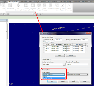
First step is to enable the Degrees from N/S setting in your Site Settings:

Then, go to a Plan View and set it to True North.  Start the Property Line tool and select Create by Entering Distances and Bearings.

Ok, basically you enter the length, the angle, and choose either N/S and E/W.  That’s it.  But what settings should you choose?

You always need to reduce your bearing dimension to something between 0 and 90 degrees (the dialog will not accept anything outside of this).  You can do this using a formula, like:

=180-140° 00′ 35″

Then you use the N/S and E/W switch to mirror or flip the dimension bearing.  In some cases, it is easier just to hit OK and see which way it is heading, then switch between the N/S and E/W settings till it looks right.  If it still doesn’t work, you may need to orient it inversely against 90 degrees, by doing something like:

=90-0° 44′ 10″

Let’s do an example.  Here is the Property Line segment we want to make:

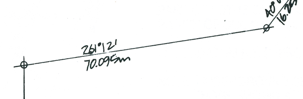
We can’t use 261 degrees, so we use a formula to minus 180 from that angle.  Then, as my previous line was using S and W, I set those to the new line.  It works!  Here is what it looks like:

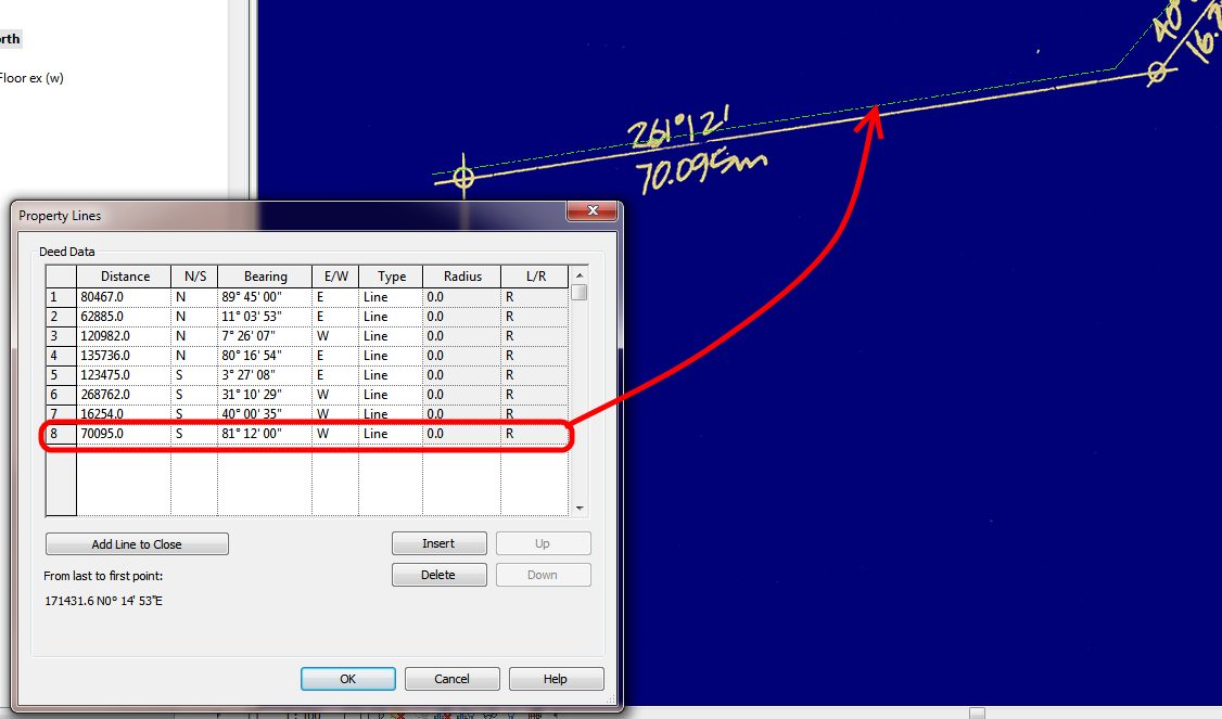
You can see that my line is slightly off the background image – this will be fixed once the whole boundary has been input (it can be moved at that point).

To reduce the above unit entry process into a simple step-by-step:

  1. Using an inplace formula, subtract 90,180 or 270 from the bearing to make it less than 90.
  2. Choose a quadrant into which the line will protrude from a given starting point -NE,SE,SW,NW
  3. If the line still does not match, subtract the bearing from 90 to correct it (flip within the target quadrant).

Good things about Revit Property Lines based on tables:

  • You can quickly check the data
  • Data can be changed relatively easily
  • Closing line can be added

Bad things:

  • Can be slow and repetitive

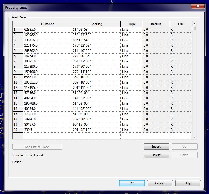
Interestingly, once you have created your Property Line, you can turn off the NS/EW setting in Site Settings, and when you Edit the Table, it will show all boundaries related to True North:

Further reading:
Property Lines by Distances & Bearings missing N/S and E/W – The Revit Clinic

Revit Architecture 2010 User’s Guide: Creating Property Lines with Survey Data

RevitCity.com | Property Lines

I would love to be able to press one button and see all of the current Autodesk products that I have installed disappear.  No, I’m not souring on Autodesk 🙂  It’s just that often the different suites and products do not play nice when trying to install them in an environment with existing Autodesk products of the same generation.

Autodesk has provided some tools to automatically uninstall certain products:

How to perform an automated uninstallation of the AutoCAD Design Suite 2013 family of products
The provided uninstall tool will detect and uninstall 32-bit or 64-bit versions of AutoCAD Design Suite 2013 (English only).

ADSUninstallTool.exe (exe – 844Kb)

How to perform an automated uninstallation of AutoCAD 2012 and Autodesk Design Suite 2012 Family Products
The uninstall tool will remove folders and registry keys related to the uninstalled product and plug-ins.

psebuninstalltool.exe (exe – 846Kb)

Unfortunately, I can not find tools to uninstall all Autodesk products of all generations, nor can I find specific tools to uninstall Building Design Suites. Can you find anything?

Try this:
Make sure that you are using the Face option for placing the component.
Turn off the Original Path by selecting the Divided Path and using:

Start the place Component command.
Make sure that you pick a Node on the Divided Path to place the Component.

The Repeat button should now be visible.

Note: you can set a Node of the Divided Path as a workplane (the Placement Plane dropdown in the Options bar will read “Divided Path”), but placing a Component on such a workplane will likely mean that the Repeat button will be grayed out.

Aaron Maller has been travelling a lot lately, but he still found the time to upload some of the recent presentations that he has delivered:


Flicking through the Glasgow RUG PDF, you will find cool stuff like:
 
 
I also like these words from his post:

Its really not enough to be doing the best that i can in one country.

We need a vehicle, for reaching a Global platform.

i dont post these thinking they are anything more than what they are:  One small groups workflow that happens to get us through some specific needs.

Read more / via:
Malleristic Revitation: Malleristic BIM travels

I think Civil3D is a very powerful and useful tool.  I have even found some ways to make it work nicely with Revit, by using it to do graphical slope analysis, or using it to increase Topography resolution.

If you too are interested in using Civil3D in the BIM process, you should check out the recent article by Andrew Walther on AUGI:

Quote:
As can be seen, the concepts of BIM, which were initially founded in the building industry, can readily be applied to infrastructure and land development projects.  The key lies in understanding the processes and applying those concepts to the individual components of the process.  Whether it’s BIM or Model-Based Design, the concepts are the same and the technology allows designers to share and leverage data in certain areas.  With Civil 3D the true BIM components lie in: 1) moving data through the various phases of the infrastructure project procurement process; and 2) sharing data during individual project phases.

Read more:
BIM and Civil 3D – Fact or Fiction? | AUGI