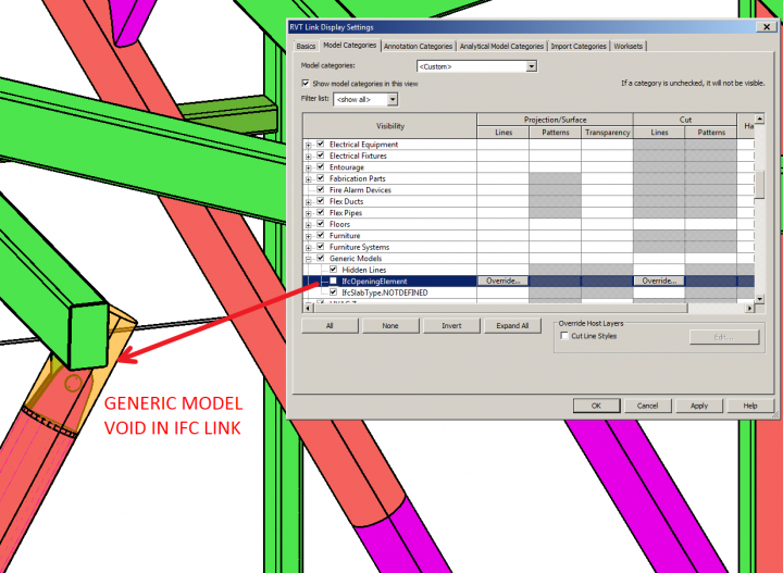
In Revit 2015, you can use the IfcOpeningElement subcategory of Generic Models (and possibly other categories) for a Linked IFC to hide the orange “void” elements that appear in certain situations, as per this image:

Just use the Revit Links Display Settings to “override” settings in Visibility / Graphics (choose custom, and Model Categories tab also custom) to access this subcategory.

I worked with a Structural Engineer recently who used to model Void Forms in his Structural Columns so that he could “cut” them into walls and other geometry.

However, this created a bit of an issue when the Structural model was linked into the Architectural – namely, orange voids would occasionally show up, because they were not cutting anything.  Obviously, this type of scenario is not ideal, but it is actually quite common to come across modelling practices that associates or other companies use that don’t really fit directly into your own workflow. In those situations, you often need to find a workaround, or perhaps discuss this issue to try and come to a compromise.

In this case, the engineer recommended this course of action:
I just noticed some of the columns have the yellow voids displaying, this is a Revit gremlin that creeps in overtime and needs to be fixed every few days or before issuing but I forgot. I can fix it and re send alternatively if you have started working with the file, it is as simple as editing the family changing a parameter and reloading It, essentially doing a regen. The other option is to select all rectangular columns and change the parameter ‘void offset’ to say 2.

How do you deal with differing modelling practices?  Have you been able to solve these issues, or have they become permanent headaches?  At Virtual Built, it is our primary goal to make teams function more efficiently throughout the entire BIM process.  Do you have a problem that needs solving?  Or do you have a great workflow solution that you would like to share?  Feel free to contact us.  Let’s collaborate!
http://bit.ly/MuT5fT

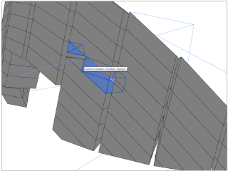
You may have struggled to cut a pattern based form with a loaded void, where you have modelled extrusions  or other forms directly into the Pattern based family template.

If you actually replace your plain extrusion forms with a nested Adaptive Generic Model in the Pattern Based template, you will be able to cut it with a Loaded Component, such as my SuperVoid family.

From Philip Chan’s blog:
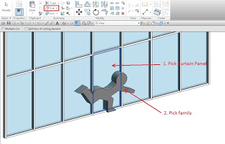
The concept is simple, I make a Generic family (it can be any category actually) as a solid (in this case, just a simple extrusion), let the family intercept the curtain wall, then use “Cut Geometry” to cut out the curtain panel.

Once I made all the cut in the curtain wall, I have a yes/no parameter to control the visibility of the solid so that I can “turn off” the solid. As a result, it would appear that the curtain wall is cut out by a void. The good news is you can use the same family to make multiple cuts and it will work on the mullions as well.

Read more:
http://phil-osophyinbim.blogspot.co.uk/2013/08/curtain-wall-and-engraving.html

Ever wanted to “hide” a void, or stop it from cutting?  There are at least two ways:

1) parametrically moving the void outside of the solid form when you dont want it to cut (this is the “old way”)

or this interesting solution via Twitter:
2)