I have recently developed a few Material and Object Procurement and Tracking solutions, primarily using Deep Space and Revizto together. These workflows also involved IFCs converted into Revit, so we could automatically set tracking parameters from Deep Space data back into Revit, and colourise the models. When converting Revit to IFC, I usually use IFC Link functionality, primarily for speed and geometric integrity.


However, some DirectShape objects created by IFC Link cannot be overridden in Revit using traditional methods. Even after setting Revit parameters from Deep Space, and using Visibility/Graphics Filters, the elements simply will not allow their colours to be overridden using a Shaded Surface pattern. So, we have to find another way…


It turns out that Phase Filters are really the only way to solve this problem, as they override the elements at the Material level. There are a few pieces to the puzzle:

  1. Set up the necessary Phase Filter, with each item set to Overridden (this allows for basically 4 status overrides in total)
  2. Set Graphic Overrides – Material definitions to have the colours you want (by changing Phase – Exist material etc to the desired colour / material)
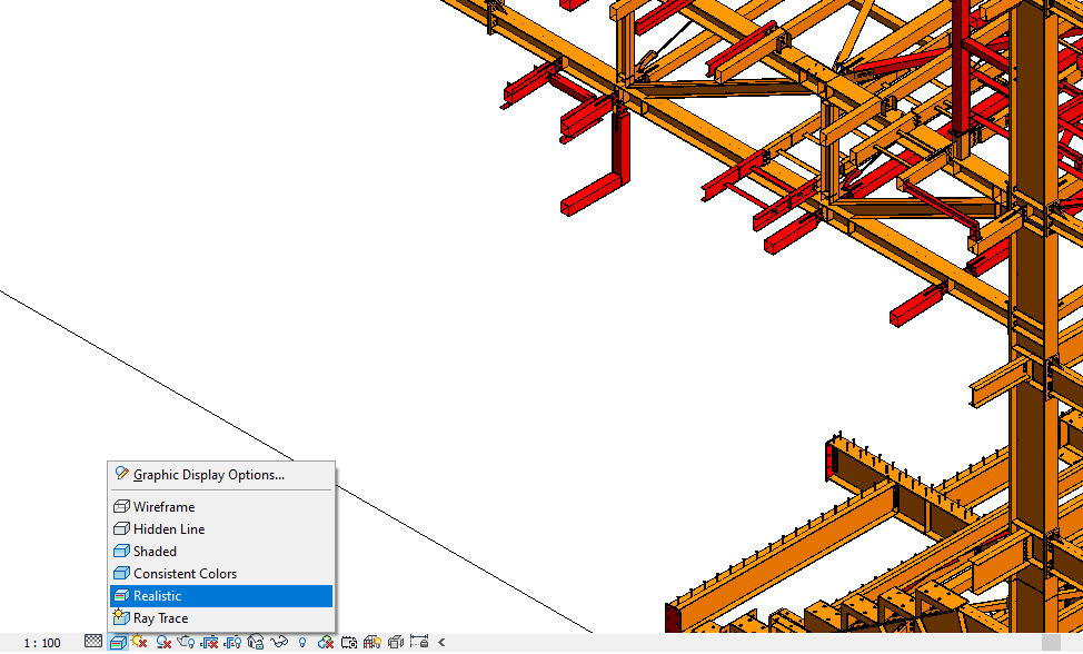
  3. Set the Revit view to the correct Phase and Phase Filter, and Realistic view mode

Here are some screenshots of the above steps:

1 - Create Phase filter for visual Overrides
1 – Create Phase filter for visual Overrides

Next…

2 - Edit Revit Material to match desired visual Overrides
2 – Edit Revit Material to match desired visual Overrides

Then…

3 - Set the View Settings
3 – Set the View Settings


Also…

Keep in mind if you are using Container Files you will need to Transfer Project Settings and bring across your
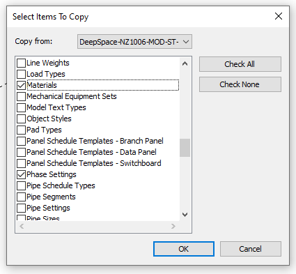
 

Finally…

Make sure your View is set to Realistic in Revit, if you truly want to see the Material Phase override in the Revit view.

Update… v2 has been published in Bakery package as:
Create Floors From Rooms v2.dyf

All kinds of weirdness with Package Manager at the moment, so I am sharing my entire ‘packages’ folder including Bakery and dependencies for 0.8.2 at this link:
https://drive.google.com/open?id=0B1dGdRkpk2beekFydmdCZTVhc0k

It uses a two different methods to get Room Boundary outlines: first try is with a Clockwork node, next try is by Element.Geometry. It also sets the Room Number to the newly created Floor Comments parameter.

Just letting you all know that this new node has just been published in the Bakery package:
Create Floors From Rooms v1.dyf

The scope:
This ‘version 1’ node takes the Room elements, converts to Element.Geometry, grabs the face at the host level, gets the curves from the face, uses Konrad Sobon’s Group Curves node to assist with making the Polycurves, then matches the right Polycurve with the outer boundary using a bounding box method. Then, it feeds the outline to a Floor creation node (after matching link Level-host Level if necessary), and then sets Element Id, Room Number and Room Name as one string to the parameter you select.

You can use it across links with some other Bakery nodes too, which would look something like this:

Unfortunately, sometimes the builtin Element.Geometry node will fail to convert the Room to a solid. This warrants further investigation, but only affected about 15 rooms of 718 in this particular test. In the meantime, I simply report which rooms fail in the ‘geometry failure’ output:

Future improvements needed:

  • handle Element.Geometry failures with some other method
  • cut out Floor Openings where voids are present in the Room space
  • match Base Offsets by moving created floors to correct height
  • get approximate Room Height by Volume and drive or report desired Floor Thickness

Here is the 1 minute demo:

And the dyn:
http://gdurl.com/cWYz

If you are on Dynamo 0.9 or newer, you may want to check out Marcello’s Direct Shape method over at:
Simply Complex: Create 3D Rooms in Revit Using DynamoBIM