Did you ever notice this little button, available in the Manage Images dialog in Revit 2015?

Although it is pretty self-evident, here you can replace an image by reloading from a different one. You can also use the Reload button to reload an image from the ‘saved path’.

Example:
 

This was a platform enhancement in 2015, as per:
About Managing Images | Revit Products | Autodesk Knowledge Network

You can read more about it at:
About Managing Images | Revit Products | Autodesk Knowledge Network

Once you have imported an image into Revit and then warped it (by unticking the Lock Proportions box and resizing it), then it is not immediately evident how you can reset it to 1:1 (its default X:Y state).  Even if you toggle the tick box, it doesn’t reset the scale to be un-warped.

Here is how you can do it:

  1. Select image and Edit Type
  2. Take note of the pixel sizes
  3. Directly set the image size using these values in the instance properties
  4. Tick the Lock Proportions box

Also, did you notice that Revit records where the image was originally loaded from?  Even though there is no ‘link’ as such, this does allow you to find and edit the source image easily.

    In Revit 2013, the Properties Palette does not expose the Graphic Display Options button in the Family Environment:

    However, you can still get to the Graphic Display Options by using the View Control Bar:

    This is handy, because it lets you use the nice Transparency slider while editing complex families or when tracing over Raster Images.

    On a side note, if you ever want to know what each part of the User Interface in Revit is officially called, check out this link.

    You have a scanned image of a Contour Plan, and you want to convert that raster image into useful vector data.  How do you go about it?

    In the past, I would have used vanilla AutoCAD to trace the contours to polylines, then I might ‘spline’ them, then convert back to polylines (using a LISP tool), set all the elevations properly, and then import to Revit, then Create from Import to make the Topography.  Fun!

    However, this week I have fallen in love with a new tool.  Its called AutoCAD Raster Design.  I’ll admit – it’s not perfect.  But it is smart, and it makes the process much more bearable.  Just follow these steps:

    1. Download the AutoCAD Raster Design trial from here
    2. You need vanilla AutoCAD installed already…
    3. Install AutoCAD Raster Design
    4. Scan your image using scanning software.  Save as pretty much any format, such as a JPG.
    5. Open Raster Design.
    6. Click ‘Insert Image…’
    7. Just do Quick Insert to get your image in quickly.
    8. Now use the Histogram tool from the Raster – Image Processing menu.  Try and get a lot of ‘contrast’ into your image.
    9. Use the ‘Change Color Depth’ tool from the Raster – Image Processing menu.  Reduce to Grayscale and then Bitonal.  You really need to get the image into a ‘Bitonal’ form to make use of the vectorization tools.
    10. Use the Despeckle tool from the Raster – Cleanup menu to get rid of little dots…
    11. Now that you have a nice clean Bitonal Image, go to the Raster – Vectorization tools menu and choose ‘Contour Follower’.  This tool is pretty self explanatory – just follow the command prompts and experiment with the options on the command line.
    12. You may need to tweak the ‘Options’ under the Raster menu – Options.  On the Raster Entity Detection tab, tweak these settings to suit your image.  Also under the VTools Follower tab, tweak these settings to suit your Elevation Interval…
    13. Finally, you will want to turn on Raster Snap under the Raster menu.  This will snap to the Bitonal image elements quite nicely.

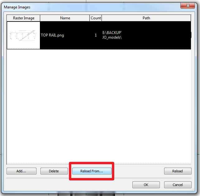
    Once you have traced all your contours and set proper elevations, save the DWG.  You will be prompted to also save the image…

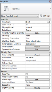
    Now import your DWG into Revit and use it to make your Topography.

    Obviously, what Revit wants is for you to use accurate data at all times – so if you can get access to a proper DWG of the Contour Plan, do that!  In the meantime, you can use the abovementioned process to get the project under way…

    raster-2975375

    Let’s say you have imported an image of an existing floor plan into a Revit view, but it doesn’t quite look right. When you scale the image, it appears to be warped in either the ‘X’ or ‘Y’ direction.

    What do you see in the ‘Options’ bar? Untick the box ‘Lock Proportions’ and you can correct the warped image by resizing with the blue grips!

    While you’re at it, if you want the ‘Options’ bar to appear at the bottom of your screen, right click on the ‘Options’ bar and select ‘Dock at Bottom’.

    So, you try and print a view with an image in it, and Revit 2010 just decides to crash…and you can’t figure it out!

    Well, Revit wants you to choose ‘Raster’ instead of ‘Vector’ under the ‘Print’ dialog – ‘Setup’ button…

    There you go, no more crashing!

    I have reported this to Autodesk (see below 😉

    Summary: Printing ‘linked view’ with image – crashes
    Description: When printing a host view with a linked RVT view that contains a high res image.

    The same problem occurs if printing the drawing from the linked file (the image seems to crash revit).

    However, changing the print type to ‘raster’ solves the problem. Revit should realise that ‘vector’ is going to crash, and switch to ‘raster’ automatically.

    Please correct this problem as it is irritating.

    So, someone has inserted images into your file, and you can’t save them out!

    Sure, you can go to File – Raster Images, but that doesn’t really help.

    Try this:

    The answer is simply to ‘export’ the view to DWG, and Revit will make the images you need.

    For a nice, clean, step by step:
    1. Make a new drafting view.
    2. Select the image / images you want to ‘save out’
    3. Copy to Clipboard
    4. Paste them into the Drafting View
    5. Export to DWG
    6. Have a look at the folder that you exported to – there are your images!